Vacuum arc-extinguishing chamber

A vacuum interrupter and arc interrupter technology, which is applied to high-voltage air circuit breakers, electrical components, electrical switches, etc. The effect of flow capability

Active Publication Date: 2021-04-06
PINGGAO GRP +1
View PDF15 Cites 2 Cited by
  • Summary
  • Abstract
  • Description
  • Claims
  • Application Information

AI Technical Summary

Problems solved by technology

[0005] The purpose of the present invention is to provide a vacuum interrupter to solve the main The technical problem of not effectively improving the current flow capacity caused by the flat contact of the contacts to transfer the closing current

Method used


Image

  • Vacuum arc-extinguishing chamber
  • Vacuum arc-extinguishing chamber

Examples


specific Embodiment 1

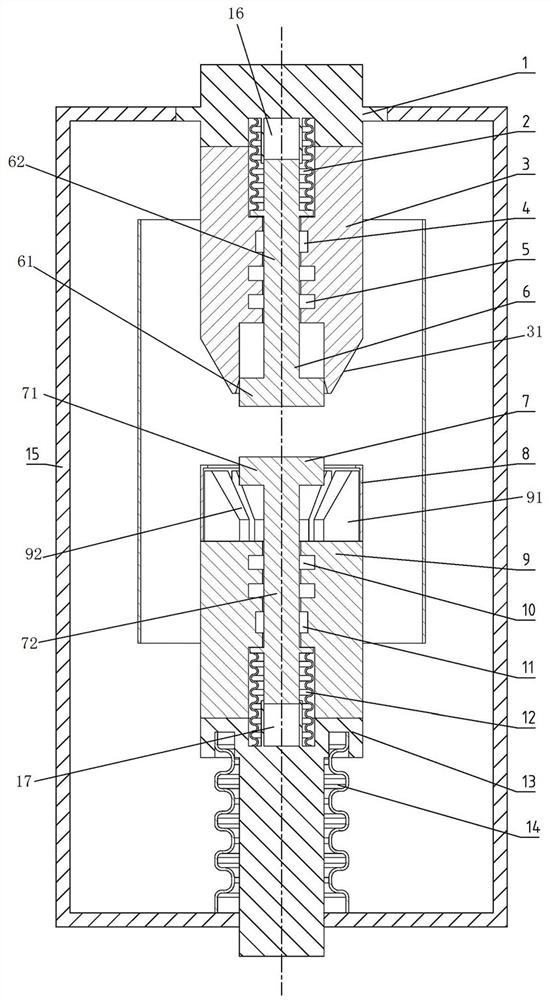
[0043] In the vacuum interrupter provided in this embodiment, both the static contact structure and the moving contact structure are composite contact structures, that is, there are main contacts and arc contacts respectively, and the outer peripheral surface of the static main contact 3 is The tapered outer peripheral surface 31, while the moving main contact 9 is provided with a tapered recess 92, the inner peripheral surface of the tapered recess 92 is a tapered inner peripheral surface, and the tapered inner peripheral surface is mated with the tapered outer peripheral surface 31 , when the switch is closed, the static main contact 3 and the moving main contact 9 can be plugged together. Since the contact surface is a conical surface, compared with the previous flat contact, it can effectively expand the flow area and reduce the Impedance, improve temperature rise performance, which can effectively improve the performance of the entire arc extinguishing chamber.

[0044] T...

specific Embodiment 2

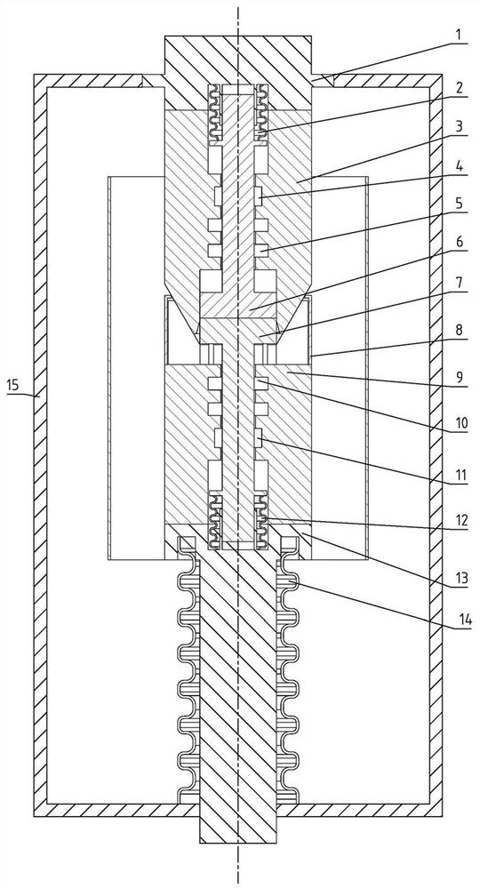
[0058] The main difference between it and Embodiment 1 is: in Embodiment 1, in the embodiment, the static main contact has a tapered outer peripheral surface, and the moving main contact has a tapered concave portion. In this embodiment, the moving main contact has a tapered outer peripheral surface, and the static main contact has a tapered concave portion, which can also realize the tapered mating of the two main contacts and effectively increase the contact area.

[0059] Generally speaking, the moving contact structure is arranged at the bottom, and the static contact structure is arranged at the top. In fact, in other embodiments, the moving contact structure can also be arranged at the top, and the static contact structure is arranged at the top. Arranged below.

specific Embodiment 3

[0061] It differs from Embodiment 1 mainly in that: in Embodiment 1, the tapered outer peripheral surface of the static main contact and the tapered inner peripheral surface of the moving main contact are both conical surfaces. In this embodiment, the tapered outer peripheral surface of the static main contact and the tapered inner peripheral surface of the moving main contact can also be pyramidal surfaces, but for the purpose of improving the electric field performance, the edges of the static main contact can be designed rounded structure.


PUM


Abstract

The invention relates to a vacuum arc-extinguishing chamber. The vacuum arc-extinguishing chamber comprises a static contact structure which comprises a static main contact and a static arc contact, the static main contact and the static arc contact are in conductive connection, the static arc contact is movably assembled in the static main contact, a moving contact structure comprises a moving main contact and a moving arc contact which are conductively connected, and the moving main contact and the static main contact are used for normal through-current, and the moving arc contact and the static arc contact are used for arc extinguishing. One main contact of the static main contact and the moving main contact is provided with a conical outer peripheral surface, the other main contact is provided with a conical concave part, the conical concave part is provided with a conical inner peripheral surface, and the conical inner peripheral surface is used for being matched with the conical outer peripheral surface in an inserted mode during closing so as to achieve normal through-current. In the vacuum arc-extinguishing chamber, the main contact and the arc contact are completely separated in the opening and closing process, the through-current capability of the vacuum arc-extinguishing chamber is effectively improved, and the through-current area can be effectively increased and the through-current capability can be improved by utilizing conical fit insertion between the movable main contact and the static main contact.

Description

technical field [0001] The invention belongs to the technical field of vacuum switches, and in particular relates to a vacuum interrupter. Background technique [0002] With the development of the economy, vacuum circuit breakers have gradually replaced sulfur hexafluoride circuit breakers due to their environmental friendliness, long life, and maintenance-free characteristics. Under normal circumstances, the rated current can be conducted, and the fault current can be interrupted under fault conditions. [0003] A vacuum interrupter is disclosed in the Chinese utility model patent with the authorized announcement number CN2023076740U. Although the static contacts include separately arranged arc contacts and main contacts, the moving contacts are still the main contacts and arc contacts. One-piece structure, even if the longitudinal magnetic field contact structure with the best breaking capacity and suitable for high voltage and large breaking capacity is adopted, the flow...

Claims


Application Information

Patent Timeline
Patent Type & Authority Applications(China)
IPC IPC(8): H01H33/664
CPCH01H33/664
Inventor 刘庆毕迎华马朝阳杨帆林麟薛从军李永林王向克李旭旭孙广雷何创伟陆静李小钊赵芳帅齐大翠刘文魁王铭飞徐伏刚王晶庞素敏刘先保李潇张航李新卫关欣李智勇周跃刚
Owner PINGGAO GRP
Why Eureka
Try Eureka