A rapid perfusion device for liver donors during liver transplantation
What is Al technical title?
Al technical title is built by PatSnap Al team. It summarizes the technical point description of the patent document.
A technology of liver transplantation and perfusion tube, which is applied in the field of liver transplantation perfusion, which can solve problems such as insufficient perfusion, inconvenient retraction, and potential safety hazards, and achieve the effects of ensuring the effect of injection, facilitating popularization and application, and improving safety
Active Publication Date: 2022-06-17
THE FIRST AFFILIATED HOSPITAL OF MEDICAL COLLEGE OF XIAN JIAOTONG UNIV
View PDF15 Cites 0 Cited by
Summary
Abstract
Description
Claims
Application Information
AI Technical Summary
This helps you quickly interpret patents by identifying the three key elements:
Problems solved by technology
Method used
Benefits of technology
Problems solved by technology
However, in this process, the intubation is prone to be too deep. At this time, the perfusate flows to the right hemihepatic roof, which may easily lead to insufficient perfusion of the left and right livers. The middle is slower, resulting in differences in left and right hepatic ischemia time
At the same time, there is no device to prevent liquid reflux in the traditional perfusion pipeline, and the liquid perfusion completely relies on gravity to enter the donor liver. During the entire perfusion process, various factors may cause the perfusate to reflux at any time, resulting in a slowdown of the perfusion speed.
[0004] According to the above, although the current Chinese patent liver transplantation liver donor fast fixed perfusion device (authorized publication number: CN104770361 B) has solved certain existing defects, there are also the following problems; 2. Although there is a sharp point for easy puncture and insertion, it is inconvenient to retract it, which brings great safety hazards to the operation. In view of this, it is necessary to design A fast perfusion device for donor liver in liver transplantation to solve the above problems
Method used
Image
Click on the blue label to locate the original text in one second.
Reading with bidirectional positioning of images and text.
Examples
Embodiment Construction
[0025] In the following, various specific details are set forth in order to provide a thorough understanding of the concepts underlying the described embodiments, however, it will be apparent to those skilled in the art that the described embodiments may be described without these specific details In some or all cases, well-known processing steps are not described in detail.
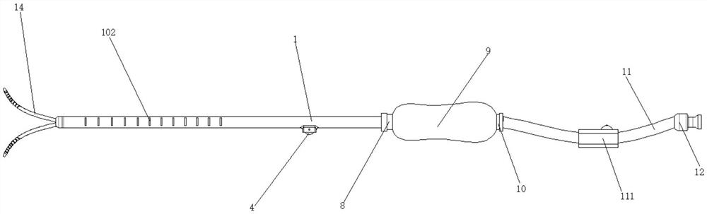
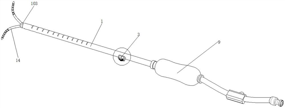
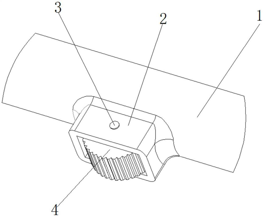
[0026] like figure 1 , figure 2 , image 3 , Figure 4 , Figure 5 , Image 6 , Figure 7 , Figure 8 , Figure 9 As shown, including perfusion tube 1, fixed sleeve 2, fixed shaft 3, toothed knob 4, spacer 5, adjustment block 6, penetrating wire 7, I one-way valve 8, liquid injection ball 9, II one-way valve 10 , connecting hose 11, interface end 12, telescopic connecting pipe 13, shunt pipe 14, separating plate 15, the fixing sleeve 2 is fixed on the right side of the outer wall of the perfusion tube 1, and the fixing sleeve 2 is integrated with the perfusion tube 1 forming, the fixed shaft 3 ...
PUM
Abstract
The invention discloses a fast perfusion device for a liver donor during liver transplantation, which comprises a perfusion tube, a fixed sleeve, a fixed shaft, a toothed knob, a spacer sleeve, an adjustment block, a penetrating wire, a one-way valve I, an injection ball, II One-way valve, connecting hose, interface end, telescopic connecting tube, shunt tube, and separation plate, first of all, through the innovative design of built-in plug-in shunt balance chamber, it can avoid the insufficient perfusion of left and right livers, and cooperate with the telescopic cone The tip of the shunt is sharp, which can not only quickly pierce the blood vessel wall and open up the blood vessel, but also can retract to avoid the continuous existence of the sharp tapered end, which improves the safety of the operation. In addition, the front end of the shunt tube is designed in a hole shape, which is convenient for perfusion The liquid flows into the liver quickly, and combined with the one-way liquid injection mechanism, it avoids the reflux situation and ensures the liquid injection effect. Promote apps.
Description
technical field [0001] The invention relates to the technical field of liver transplantation perfusion, in particular to a rapid perfusion device for donor livers in liver transplantation. Background technique [0002] At present, liver transplantation has become a routine treatment for end-stage liver disease. With the continuous promotion and improvement of liver transplantation technology in my country this year, the survival rate after liver transplantation has been continuously improved. The incidence of postoperative complications is also decreasing year by year. In liver transplantation, one of the key techniques in obtaining the donor liver is in situ perfusion of the liver. How to accurately locate and quickly perform catheter fixation and perfusion is a technical difficulty in obtaining high-quality liver sources. [0003] When traditional donor livers are obtained, the liver is quickly explored after laparotomy to find out whether there is cirrhosis, liver mass,...
Claims
Application Information
Patent Timeline
Application Date:The date an application was filed.
Publication Date:The date a patent or application was officially published.
First Publication Date:The earliest publication date of a patent with the same application number.
Issue Date:Publication date of the patent grant document.
PCT Entry Date:The Entry date of PCT National Phase.
Estimated Expiry Date:The statutory expiry date of a patent right according to the Patent Law, and it is the longest term of protection that the patent right can achieve without the termination of the patent right due to other reasons(Term extension factor has been taken into account ).
Invalid Date:Actual expiry date is based on effective date or publication date of legal transaction data of invalid patent.
Patent Type & Authority Patents(China)
IPC IPC(8): A01N1/02
CPCA01N1/0247
Inventor 师建华王博于良吕毅
Owner THE FIRST AFFILIATED HOSPITAL OF MEDICAL COLLEGE OF XIAN JIAOTONG UNIV