Welding device for electric tool part machining

A technology for electric tools and welding devices, applied in auxiliary devices, manufacturing tools, welding equipment, etc., can solve the problems of local overheating during welding time, reduce people's cleaning efficiency, and not meet the needs of use, so as to achieve smooth welding work and solve clamping problems. Difficulty, the effect that meets the needs of modern use

Inactive Publication Date: 2021-07-09
东莞市浩恒工业设计有限公司
View PDF0 Cites 0 Cited by
  • Summary
  • Abstract
  • Description
  • Claims
  • Application Information

AI Technical Summary

Problems solved by technology

[0002] Welding, also known as welding and welding, is a manufacturing process and technology for joining metal or other thermoplastic materials such as plastics by means of heating, high temperature or high pressure. In the processing of modern power tools, it is often necessary to use The welding operation of the parts, but the following problems often exist in the welding process of electric tool parts: 1. In the welding process, it is often necessary to perform multi-directional welding operations on the parts, and when multi-directional welding operations are required , it is often necessary for the staff to adjust the position of the parts in the welding process to complete the re-clamping operation, and the heated parts are often difficult to clamp, which makes the welding work cumbersome; 2. The existing parts are in the welding process. It is very easy to cause local overheating due to too long welding time, thereby causing damage to the welding parts and affecting the welding quality; 3. The existing welding device lacks a cleaning and collecting device for workbench waste, which is inconvenient to use and reduces people's safety. The cleaning efficiency does not meet the needs of modern use

Method used


Image

  • Welding device for electric tool part machining
  • Welding device for electric tool part machining
  • Welding device for electric tool part machining

Examples


Embodiment 1

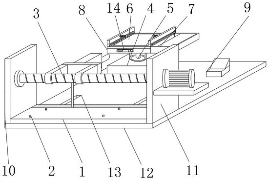
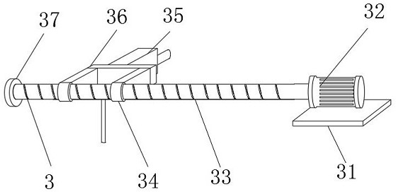
[0032] A welding device for processing electric tool parts, such as figure 1As shown, including the bottom plate 12, two No. 1 chutes 13 are opened on the front part of the upper end of the bottom plate 12, and the inside of the two No. 1 chute 13 is jointly slidably connected with the slide plate 1, and the left part of the slide plate 1 and the right part of the slide plate 1 are screwed. Fasten the knob 2, and the lower end of the fastening knob 2 is internally threaded with the two No. 1 chute 13. The left end of the skateboard 1 and the right end of the skateboard 1 are respectively fixedly connected to the No. 1 side plate 10 and the No. 2 side plate 11, and the No. 2 side plate 11 The upper part is penetrated with a welding mechanism 3, the left end of the welding mechanism 3 is fixedly connected with the right end of the No. Behind the mechanism 3 and to the left of the numerical control table 9, a driving device 5 is fixedly installed inside the cabinet 4, and the upp...

Embodiment 2

[0035] On the basis of Example 1, as Figure 2-4 As shown, a welding device for processing electric tool parts includes a base plate 12, two No. The left part and the right part of the skateboard 1 are threadedly connected with a fastening knob 2, and the lower end of the fastening knob 2 is internally threaded with two No. No. 2 side plate 11, welding mechanism 3 runs through the upper part of No. 2 side plate 11, the left end of welding mechanism 3 is fixedly connected with the right end of No. 1 side plate 10, and the upper right part of the bottom plate 12 is fixedly equipped with a numerical control table 9, and the left part of the upper end of the bottom plate 12 is fixed. A chassis 4 is installed, and the chassis 4 is located behind the welding mechanism 3 and on the left of the numerical control table 9. The drive device 5 is fixedly installed inside the chassis 4, and the upper end of the drive device 5 and the upper end of the chassis 4 are fixedly connected with a ...

Embodiment 3

[0038] On the basis of Example 1, as Figure 5-7 As shown, a welding device for processing electric tool parts includes a base plate 12, two No. The left part and the right part of the skateboard 1 are threadedly connected with a fastening knob 2, and the lower end of the fastening knob 2 is internally threaded with two No. No. 2 side plate 11, welding mechanism 3 runs through the upper part of No. 2 side plate 11, the left end of welding mechanism 3 is fixedly connected with the right end of No. 1 side plate 10, and the upper right part of the bottom plate 12 is fixedly equipped with a numerical control table 9, and the left part of the upper end of the bottom plate 12 is fixed. A chassis 4 is installed, and the chassis 4 is located behind the welding mechanism 3 and on the left of the numerical control table 9. The drive device 5 is fixedly installed inside the chassis 4, and the upper end of the drive device 5 and the upper end of the chassis 4 are fixedly connected with a ...


PUM


Abstract

The invention discloses a welding device for electric tool part machining. The welding device for electric tool part machining comprises a bottom plate, two first sliding grooves are formed in the front portion of the upper end of the bottom plate, the interiors of the two first sliding grooves are jointly and slidably connected with a sliding plate, and the left portion and the right portion of the sliding plate are both in threaded connection with fastening rotary knobs; and the lower ends of the fastening rotary knobs are in threaded connection with the inner parts of the two first sliding grooves, a first side plate and a second side plate are fixedly connected to the left end and the right end of the sliding plate correspondingly, a welding mechanism penetrates through the upper portion of the second side plate, the left end of the welding mechanism is fixedly connected with the right end of the first side plate, and a numerical control table is fixedly installed on the right portion of the upper end of the bottom plate. According to the welding device for electric tool part machining, multidirectional welding operation can be achieved, the problem that heated parts are difficult to clamp is solved, local overheating of the parts caused by too long welding time in the subsequent machining process can be avoided, and the welding quality is guaranteed; and in addition, cleaning efficiency can be improved, and modern use requirements are met.

Description

technical field [0001] The invention relates to the technical field of electric tools, in particular to a welding device for processing electric tool parts. Background technique [0002] Welding, also known as welding and welding, is a manufacturing process and technology for joining metal or other thermoplastic materials such as plastics by means of heating, high temperature or high pressure. In the processing of modern power tools, it is often necessary to use The welding operation of the parts, but the following problems often exist in the welding process of electric tool parts: 1. In the welding process, it is often necessary to perform multi-directional welding operations on the parts, and when multi-directional welding operations are required , it is often necessary for the staff to adjust the position of the parts in the welding process to complete the re-clamping operation, and the heated parts are often difficult to clamp, which makes the welding work cumbersome; 2....

Claims


Application Information

Patent Timeline
Patent Type & Authority Applications(China)
IPC IPC(8): B23K37/00B23K37/04
CPCB23K37/00B23K37/0443
Inventor 肖旭贺娜赵枟
Owner 东莞市浩恒工业设计有限公司
Why Eureka
Try Eureka