Auxiliary emergency braking device for electric automobile, and using method thereof

A technology for emergency braking and electric vehicles, which is applied in the direction of braking transmission devices, foot-operated starting devices, brakes, etc., which can solve problems such as difficult pressure differences, traffic accidents, and labor, so as to reduce the probability of traffic accidents and reduce the overall Pressure requirements, the effect of reducing the impact injury of members

Inactive Publication Date: 2021-07-23
李强
View PDF0 Cites 0 Cited by
  • Summary
  • Abstract
  • Description
  • Claims
  • Application Information

AI Technical Summary

Problems solved by technology

[0004] The motor replaces the engine in the new energy vehicle, and the vacuum for the brake booster is provided by the electric vacuum pump. Compared with the shutdown of the engine failure, the probability of the vehicle running out of power or failing to supply power due to power failure is higher. When the power supply is unstable or fails, the vehicle It may not be possible to brake urgently or brake in time because the brakes are too laborious, so that the vehicle cannot stop in time and a traffic accident may occur
[0005] Furthermore, in fact, when the electric vehicle loses power, since the vacuum pump is still in a vacuum environment, it is still in the power assist state after the first step on the pedal, but if it stops with one foot, it may affect other vehicles behind. When the vehicle is stepped on for the second time, since the vacuum pump sucks in more air at this time, the air pressure drop is limited, and it is difficult to form the required pressure difference to provide brake boosting, so the ability to boost the brakes is often lost when the brakes are stepped on for the second time.

Method used


Image

  • Auxiliary emergency braking device for electric automobile, and using method thereof
  • Auxiliary emergency braking device for electric automobile, and using method thereof
  • Auxiliary emergency braking device for electric automobile, and using method thereof

Examples


Embodiment Construction

[0020] The following will clearly and completely describe the technical solutions in the embodiments of the present invention with reference to the accompanying drawings in the embodiments of the present invention. Obviously, the described embodiments are only some, not all, embodiments of the present invention. Based on the embodiments of the present invention, all other embodiments obtained by persons of ordinary skill in the art without making creative efforts belong to the protection scope of the present invention.

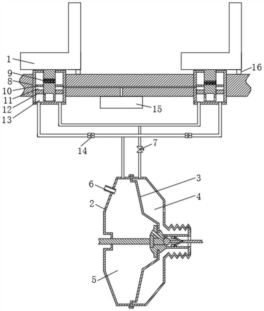
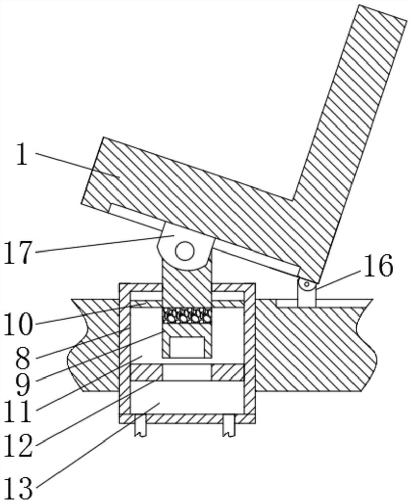
[0021] see figure 1 , an auxiliary emergency braking device for an electric vehicle and a method of use thereof, comprising a seat 1 and a booster 2, the booster 2 is provided with a diaphragm partition 3, and the two sides of the diaphragm partition 3 are respectively connected with The brake pump push rod and the pedal push rod, the diaphragm diaphragm 3 divides the inner cavity of the booster 2 into a high pressure chamber 4 and a negative pressure chamber ...


PUM


Abstract

The invention relates to the technical field of new energy automobile equipment, and discloses an auxiliary emergency braking device for an electric automobile, and a using method thereof. The auxiliary emergency braking device comprises a seat and a booster, a diaphragm partition plate is arranged in the booster, and the inner cavity of the booster is divided into a high-pressure chamber and a negative-pressure chamber by the diaphragm partition plate. According to the auxiliary emergency braking device for the electric automobile, sufficient auxiliary pressure is provided for braking through chemical energy release of a driving gas tank, it is ensured that the vehicle losing power can be rapidly stopped when encountering an emergency situation, then energy release of the driving gas tank is divided into a plurality of processes, the auxiliary driving devices correspond to negative-pressure auxiliary driving, high-pressure auxiliary driving and gravity auxiliary driving processes respectively, brake assistance is provided for more times, the angle of a seat is adjusted to be inclined upwards before a vehicle is braked, the distance between the head and chest of a passenger and a front console is increased, and when an accident occurs, the auxiliary driving device is matched with a safety belt to better reduce member injuries.

Description

[0001] The application date is September 24, 2020, the application number is CN 202011016732.1, and the title of the invention is a divisional application for an auxiliary emergency braking device for electric vehicles. technical field [0002] The invention relates to the technical field of medical equipment, in particular to an auxiliary emergency braking device for an electric vehicle and a usage method thereof. Background technique [0003] When the car is running at high speed, it needs a large braking force to stop it completely. Therefore, at this time, it needs a large pedaling force to achieve braking. The current vehicles are equipped with brake boosters. The power of the resistance comes from the intake manifold of the engine. After the pedal is stepped on, the opening state of the valve is changed, so that the interior of the booster is divided into two mutually closed cavities, and the side connected to the intake manifold of the engine generates negative pressur...

Claims


Application Information

Patent Timeline
Patent Type & Authority Applications(China)
IPC IPC(8): B60T13/46B60T13/52B60N2/06B60N2/10B60T7/06
CPCB60N2/06B60N2/10B60T7/06B60T13/46B60T13/52
Inventor 李强
Owner 李强
Why Eureka
Try Eureka