

Vehicle cleaner unit and vehicle cleaner system
A technology for cleaners and vehicles, applied in the direction of vehicle cleaning, cleaning methods and appliances, and cleaning methods using gas flow, etc., can solve problems such as lens staining, achieve the effect of preventing the intrusion of water, etc., and saving space
- Summary
- Abstract
- Description
- Claims
- Application Information
AI Technical Summary
Problems solved by technology
Method used
Image

Examples
no. 1 approach
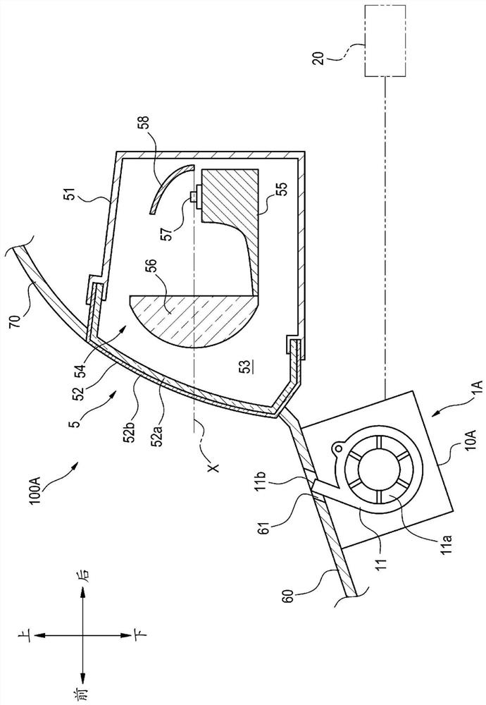
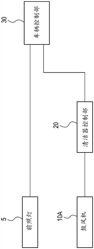
[0170] figure 1 It is a longitudinal cross-sectional view of 100 A of cleaning systems for vehicles (hereinafter, referred to as cleaning system 100A) of the first embodiment. Such as figure 1 As shown, the cleaning system 100A includes a vehicle cleaner unit 1A (hereinafter, referred to as the cleaner unit 1A), and a headlight 5 (an example of a cleaning object). The cleaning system 100A is a cleaning system mounted on a vehicle for cleaning objects to be cleaned such as headlights 5 . In the description of the present embodiment, for convenience of description, "left-right direction", "front-back direction", and "up-down direction" are appropriately mentioned. These directions are relative directions set for a vehicle on which cleaning system 100A is mounted.
[0171] The headlamp 5 is mounted near the front bumper 60 . For example, the headlight 5 is mounted in an installation space formed between the hood 70 of the vehicle body and the front bumper 60 . The headlamp 5...
no. 2 approach
[0200] Figure 4 It is a vertical cross-sectional view of cleaning system 100B of the second embodiment. The cleaning system 100B and the cleaner unit 1B of the second embodiment are similar to the cleaning system 100B of the first embodiment in which the blower 10B is attached to the frame body 51 of the headlight 5 in the second embodiment. System 100A and cleaner unit 1A are different. The function of the blower 10B is the same as that of the blower 10A described in the first embodiment. Also, as in the first embodiment, the front bumper 60 is opened with an air outlet 61 for blowing the air blown out from the blower 10B toward the headlight 5 .
[0201] As described above, according to the washer unit 1B of the second embodiment, the blower 10B is attached to the housing 51 of the headlight 5 , and the air outlet 61 is opened in the front bumper 60 . Therefore, air can be efficiently blown out from the blower 10B to the cover 52 of the headlamp 5 . In addition, the blo...
no. 3 approach
[0204] Figure 5 It is a transverse cross-sectional view of 100 C of cleaning systems of 3rd Embodiment.
[0205] Such as Figure 5 As shown, a cleaning system 100C of the third embodiment includes a cleaner unit 1C and a headlight 5 . The cleaner unit 1C includes a blower 10C and a cleaner control unit 20 .
[0206] The blower 10C is attached to the back of the front grille 80 disposed between the left and right headlights 5 and to the side of the headlights 5 . Figure 5 The headlight 5 shown in is the headlight 5 mounted on the right side of the vehicle, and is arranged between the front grille 80 and the body panel 85 on the side of the vehicle in plan view. Therefore, the blower 10C is arranged behind the front grille 80 and on the left side of the right headlight 5 . In addition, although illustration is omitted, the blower 10C may be arranged on the back of the front grille 80 and on the right side of the left headlight with respect to the left headlight.
[0207] ...
PUM
 Abstract
Description
Claims
Application Information