Lifting type printing and drying mechanism for corrugated boards

A technology for printing drying and corrugated cardboard, which is applied in printing, printing devices, and dispersed particle filtration, etc. It can solve the problems of inconvenient adjustment of the printing nozzle and the drying structure of corrugated cardboard, affect the printing and drying effect, and achieve ink stimulation. Eliminate irritating odors, correct the direction of materials, and achieve the effect of lubrication and anti-wear

Inactive Publication Date: 2021-09-28
许金祥
View PDF9 Cites 2 Cited by
  • Summary
  • Abstract
  • Description
  • Claims
  • Application Information

AI Technical Summary

Problems solved by technology

[0010] The purpose of the present invention is to provide a lifting type printing and drying mechanism for corrugated cardboard to solve the above-mentioned background technology when the thickness of the corrugated cardboard changes, the printing nozzle and the drying structure are inconvenient to adjust relative to the corrugated cardboard, thereby affecting printing. and the problem of drying effect

Method used


Image

  • Lifting type printing and drying mechanism for corrugated boards
  • Lifting type printing and drying mechanism for corrugated boards
  • Lifting type printing and drying mechanism for corrugated boards

Examples


Embodiment 1

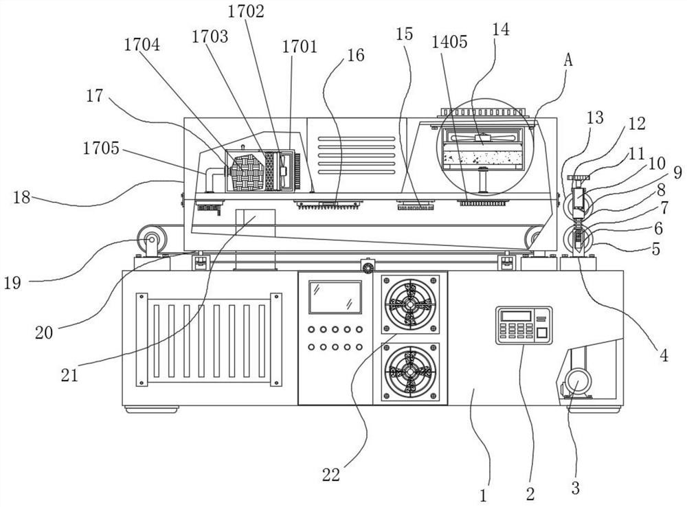
[0041] Example 1: as figure 1 , Figure 7 , Figure 8 A lifting type printing and drying mechanism for corrugated cardboard includes a first box body 1, a controller 2 is fixedly connected to one side of the front end of the first box body 1, and a conveyor belt 19 is arranged at the top of the first box body 1, The front and rear ends of the top end of the first box body 1 are fixedly connected with a support plate 20 , a lift chute 201 is arranged on the support plate 20 , a horizontal plate 202 is fixed in the lift chute 201 , and a support swivel 203 is rotatably installed on the horizontal plate 202 , a transmission gear 204 is fixed on the support swivel 203, a compression spring 205 is arranged between the upper end of the transmission gear 204 and the upper end of the lifting chute 201, the inner ring side of the transmission gear 204 is connected with a lifting screw 206 through a thread, and the upper end of the lifting screw 206 is lifted by a lifting screw The up...

Embodiment 2

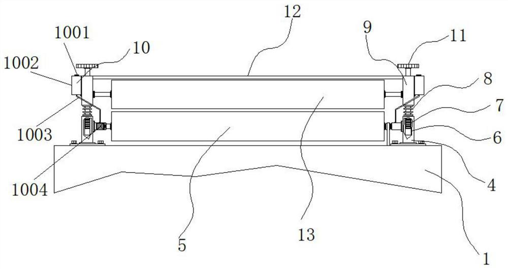
[0043] Example 2: On the basis of Example 1, please refer to Figure 1-6 , a drive motor 3 is fixedly connected to one side of the inner bottom end of the first box body 1, the specific model of the drive motor 3 can be Y90S-2, and one side of the top end of the first box body 1 is fixedly connected to a support seat 4, the support seat 4 A driving roller 5 is movably connected therebetween through a fixed bushing, a fixed block 9 is arranged above the support base 4, a pressing roller 13 is movably connected between the fixed blocks 9, a connecting rod 12 is fixedly connected between the fixed blocks 9, and the support base The top of 4 is provided with a compression tightness adjustment structure;

[0044] see Figure 1-6 , the compression tightness adjustment structure includes a threaded cavity 6, the threaded cavity 6 is arranged inside the support seat 4, the top end of the support seat 4 and the bottom end of the fixing block 9 are fixedly connected with a support spri...

Embodiment 3

[0047] Embodiment 3: The front end of the fixed block 9 is provided with a lubricating structure 10. The lubricating structure 10 is composed of a sealing cover 1001, an oil storage box 1002, a conduit 1003, an oiling ring 1004 and a foam ring 1005. The oil storage box 1002 is fixedly connected to the fixed The front end of the block 9 and the top of the oil storage box 1002 are fixedly connected with a sealing cover 1001. The oiling ring 1004 is arranged inside the fixed shaft sleeve on one side of the support seat 4. The top of the oiling ring 1004 and the bottom end of the oil storage box 1002 are connected A conduit 1003 is fixedly connected between them, and a foam ring 1005 is arranged at the top of the oiling ring 1004;

[0048] Small holes are evenly arranged inside the foam ring 1005, and the inside of the conduit 1003 and the oiling ring 1004 are communicated;

[0049] Specifically, as figure 1 , figure 2 and Image 6 As shown, the sealing cover 1001 is opened, a...


PUM


Abstract

The invention discloses a lifting type printing and drying mechanism for corrugated boards, and particularly relates to the technical field of printing and drying machines. The lifting type printing and drying mechanism comprises a first box body, one side of the front end of the first box body is fixedly connected with a controller, and one side of the bottom end in a second box body is provided with a paperboard cleaning mechanism; and a pressing tightness adjusting structure is arranged at the top end of a supporting seat. A rotating handle is rotated to drive an adjusting shaft to rotate, the adjusting shaft drives a middle shaft to rotate through transmission of a middle gear, the middle shaft drives a transmission gear on a supporting plate to rotate when rotating, and due to the fact that the transmission gear is rotationally positioned on a transverse plate on a lifting sliding groove, when the transmission gear rotates, a lifting screw rod is pushed to move in a lifting sliding way; and when the lifting screw rod moves up and down, the second box body is driven to move up and down, so that the distances between a printing spray head, a pungent smell suction-away mechanism and the paperboard cleaning mechanism on the second box body and a conveying belt are adjusted to adapt to printing and drying of the corrugated boards with various thicknesses.

Description

technical field [0001] The invention relates to the technical field of printing dryers, in particular to a lift-type printing and drying mechanism for corrugated cardboard. Background technique [0002] With the development of society and the advancement of science and technology, especially the rapid rise of the e-commerce economy in recent years, the demand for various packaging materials, especially cartons, is increasing, and corrugated paper production enterprises have made a lot of profits. In the process of corrugated paper production , according to the customization requirements, it is an essential step for printing on cardboard, and the corresponding printing dryer also has shortcomings and defects with continuous use, which needs to be improved. [0003] In the process of realizing the present invention, the inventor found that at least the following problems have not been solved in the prior art: [0004] (1) The traditional lifting type printing and drying mecha...

Claims


Application Information

Patent Timeline
Patent Type & Authority Applications(China)
IPC IPC(8): B41J11/00B01D53/04B01D46/00B01D46/02B01D46/10
CPCB41J11/0022B41J11/0015B41J11/0045B01D53/0407B01D46/0039B01D46/02B01D46/10B01D2253/102
Inventor 许金祥
Owner 许金祥
Why Eureka
Try Eureka