Multifunctional rod

A multi-functional and unified technology, applied in the field of multi-functional rods, can solve the problems of consumables, etc.

Pending Publication Date: 2021-10-22
ZHEJIANG JINGRI LIGHTING TECH
View PDF7 Cites 0 Cited by
  • Summary
  • Abstract
  • Description
  • Claims
  • Application Information

AI Technical Summary

Problems solved by technology

Although the hollow part is designed, in order to ensure the stability of the groove, the thickness of the light pole at the bottom of the groove must be sufficient, and in order to ensure the stability of the groove, the distance between the groove wall and the hollow part etc. must also have a certain thickness, so in order to ensure the stability of the structure, it is necessary to strengthen the structure of the entire rod body.

Method used


Image

  • Multifunctional rod
  • Multifunctional rod
  • Multifunctional rod

Examples


Embodiment 1

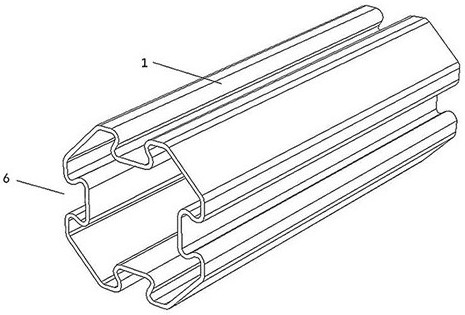
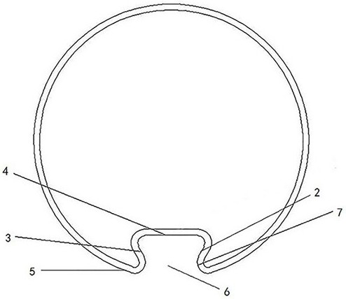
[0036] This embodiment provides a multifunctional pole 1, which is mainly used to improve the stability of the structure while saving materials. The multifunctional rod 1 includes: a first locking wall 2, a second locking wall 3, a connecting wall 4 and a supporting wall 5; the bottoms of the first locking wall 2 and the second locking wall 3 are connected by the connecting wall 4, And, the first locking wall 2 and the second locking wall 3 gradually approach outwards from the connecting wall 4 to form an installation opening 6 at their ends; the support wall 5 is arranged on both sides of the installation opening 6 and corresponds to the installation opening 6 There is a buffer angle 7 between the supporting wall 5 and the correspondingly connected locking wall.

[0037] In this example, if figure 2, the first locking wall 2 and the second locking wall 3 are folded towards the inside of the multi-functional rod 1 along one end of the connecting support wall 5, and are conne...

Embodiment 2

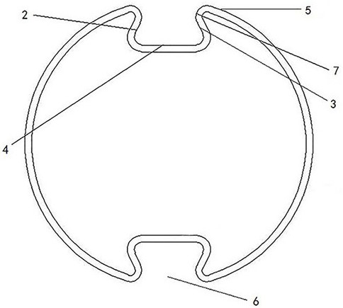
[0048] In this embodiment, different from the single installation port 6 in Embodiment 1, the multi-function bar 1 contains multiple installation ports. Due to the development of the 5G era, multiple devices need to be installed on the multi-function bar 1. The structure of a single installation port 6 is not enough to meet the needs of high-level installation of external equipment, so the number of installation ports 6 can be determined according to different environments, the number of installation devices, and the direction of installation devices. Secondly, if multiple external devices need to be installed, the multi-functional rod 1 with a single mounting port 6 can only be installed on the side of the multi-functional rod 1 containing the mounting port 6, which is likely to be affected by the pulling force of the external device at the mounting port 6. Multifunctional pole 1 for stabilization. In order to ensure the stability of the multi-function bar 1 when multiple ext...

Embodiment 3

[0050] The difference between this embodiment and the first and second embodiments above is that, as Figure 6 , the support wall 5 includes a flat support portion 5-1, the flat support portion 5-1 is arranged close to the installation opening 6, and is connected with the locking wall on the corresponding side of the installation opening 6; the flat support of the support arms on both sides of the same installation opening 6 Section 5-1 is located in the same plane. On the one hand, one end of the flat supporting part 5-1 on both sides of the installation port 6 is connected to the corresponding locking wall to strengthen the locking wall, and the other end forms a certain angle with other parts of the supporting wall 5. The included angle is the same as the buffer angle in the first embodiment, and acts as a buffer to the force received by the flat support portion 5-1. On the other hand, the flat support portions 5-1 on both sides of the mounting opening 6 are in the same pl...


PUM


Abstract

The invention belongs to the technical field of lighting mechanical technologies, and particularly relates to a multifunctional rod which is mainly used for improving structural stability while saving materials. The multifunctional rod comprises a first locking wall, a second locking wall, a connecting wall and a supporting wall; bottom parts of the first locking wall and the second locking wall are connected through the connecting wall, and the first locking wall and the second locking wall gradually get close outwards from the connecting wall to form a mounting opening in ends of the first locking wall and the second locking wall; The supporting wall is arranged at two sides of the mounting opening and connected with the locking walls on corresponding sides of the mounting opening; and buffering angles are formed between the supporting wall and each corresponding locking wall connected with the supporting wall. According to the multifunctional rod, a step of slotting on the multifunctional rod is omitted, a problem that more materials are used due to slotting on a side wall of the multifunctional rod is solved, and stability of a structure is enhanced while the used materials of the structure are reduced.

Description

[0001] The present invention is divided based on the original application document "a multifunctional pole", wherein the original application date is "20201019" and the original application number is "202011116129.0". technical field [0002] The invention belongs to the technical field of lighting machinery technology, and specifically relates to a multifunctional rod, which is mainly used for improving the stability of the structure while saving materials. Background technique [0003] With the advent of the 5G era, smart light poles have become the basis for 5G construction. The signals sent by 5G base stations installed on light poles can cover every part of the city, allowing everyone to feel the wisdom brought by 5G. Therefore, in the 5G era, smart street lights are an indispensable part. In recent years, smart street lights have become an area of ​​concern in urban construction. In addition to installing 5G base stations, they can also be installed with monitoring, env...

Claims


Application Information

Patent Timeline
Patent Type & Authority Applications(China)
IPC IPC(8): E04H12/00E04H12/08
CPCE04H12/00E04H12/08E04H12/085Y02B20/72
Inventor 程世友姚斌斌潘佳欢叶少军汤燕军
Owner ZHEJIANG JINGRI LIGHTING TECH
Why Eureka
Try Eureka