Postoperative drainage device for thyroid and breast surgery

A post-surgical, nail breast technology, applied in the field of medical devices, can solve the problems of increased workload of medical staff, occupation, and consumption of a large amount of hospital resources, and achieve the effect of easy drainage and nursing work, stable drainage of effusion, and reduced use

Inactive Publication Date: 2022-03-18
HENAN PROVINCE HOSPITAL OF TCM THE SECOND AFFILIATED HOSPITAL OF HENAN UNIV OF TCM
View PDF0 Cites 0 Cited by
  • Summary
  • Abstract
  • Description
  • Claims
  • Application Information

AI Technical Summary

Problems solved by technology

[0004] However, there are certain deficiencies in the above two situations. Either each patient needs to be equipped with a negative pressure machine and the negative pressure machine needs to be in working condition all the time (it takes up and consumes a lot of resources in the hospital), or the medical staff needs to be active and frequent. Manually control the air pressure environment in the drainage ball by going to and from each ward (enhancing the workload of medical staff);

Method used


Image

  • Postoperative drainage device for thyroid and breast surgery
  • Postoperative drainage device for thyroid and breast surgery
  • Postoperative drainage device for thyroid and breast surgery

Examples


Embodiment 1

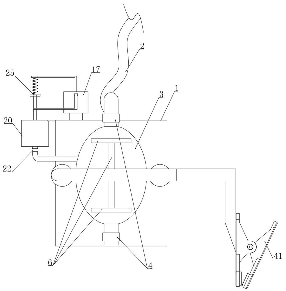
[0027] Embodiment 1, this embodiment provides a drainage device after nail breast surgery, as attached figure 1 As shown, the collection bottle 1 is included and the upper end of the collection bottle 1 is communicated with a drainage tube 2, as attached figure 1 As shown, a clip 41 is fixedly installed on the body of the collection bottle 1. When the device is in use, the medical staff can clamp it at the bedside of the patient's bed through the clip 41, and insert the drainage tube 2 into the affected part of the patient. Position to achieve drainage of postoperative effusion, as attached figure 2 As shown, the upper end of the collection bottle 1 is connected with a rubber negative pressure ball 3 through a conduit, and a first one-way valve 4 is arranged between the conduit and the rubber negative pressure ball 3, and between the rubber negative pressure ball 3 and the outside atmosphere. image 3 As shown, the setting of the two first one-way valves 4 satisfies that the...

Embodiment 2

[0033] Embodiment 2, on the basis of embodiment 1, as attached Figure 4 , 6 As shown, a cylinder 10 is fixedly installed on both sides of the spacer frame 5 in the longitudinal direction, and the fixed magnet 7 and the rotating magnet 8 are respectively arranged in the corresponding cylinder 10 (the inner wall of the cylinder 10 is provided with a magnetizer to realize Fixed magnet 7, conduction of magnetic field lines of rotating magnet), as attached Figure 10 As shown, it is a sectional view of the installation relationship between the fixed magnet 7, the rotating magnet 8 and the cylinder 10 (the N pole of the fixed magnet and the S pole of the rotating magnet 8 are on the same side, the S pole of the fixed magnet and the N pole of the rotating magnet 8 are on the same side, and the magnetic field lines between them are in the same direction as Figure 14 shown in the middle left view), as attached Figure 11 As shown, the rotating magnet 8 rotates coaxially with a rou...

Embodiment 3

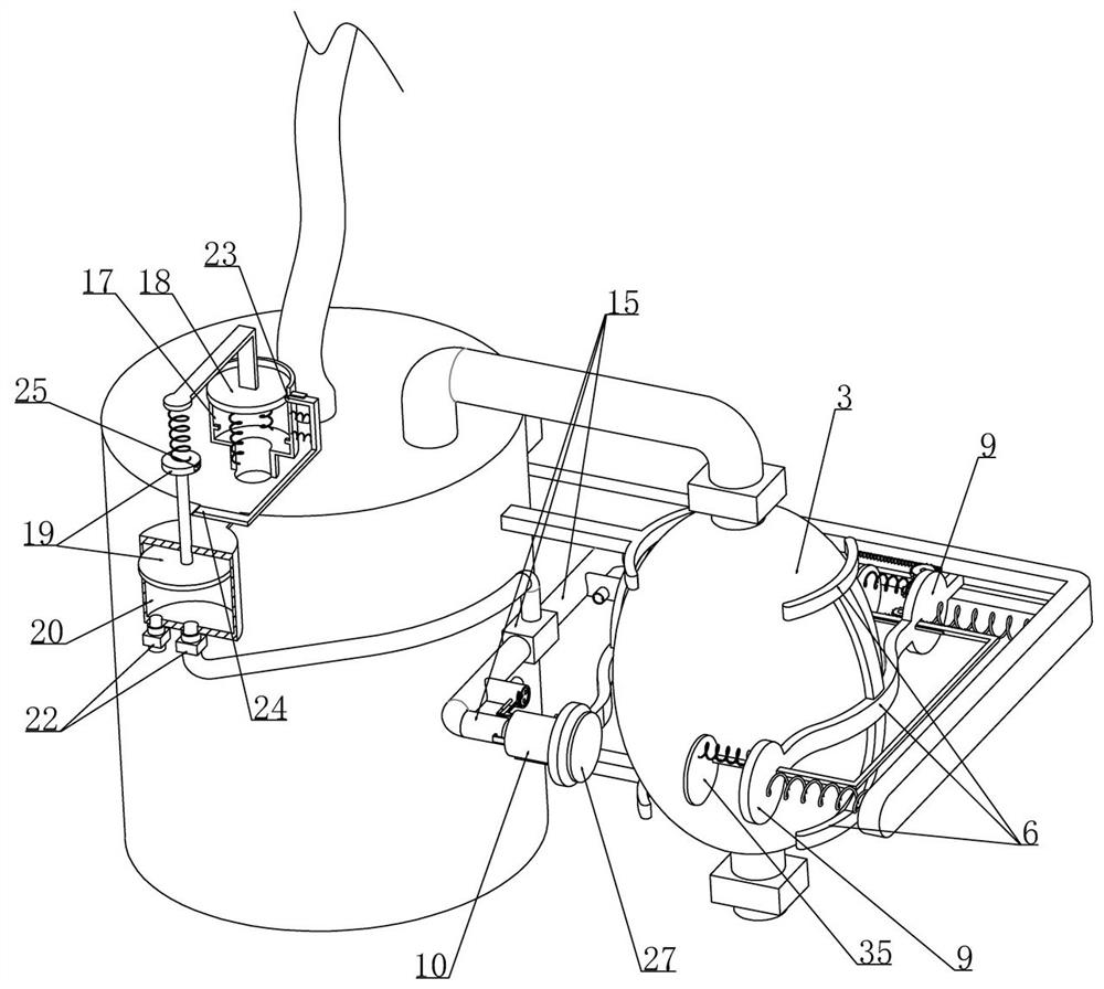
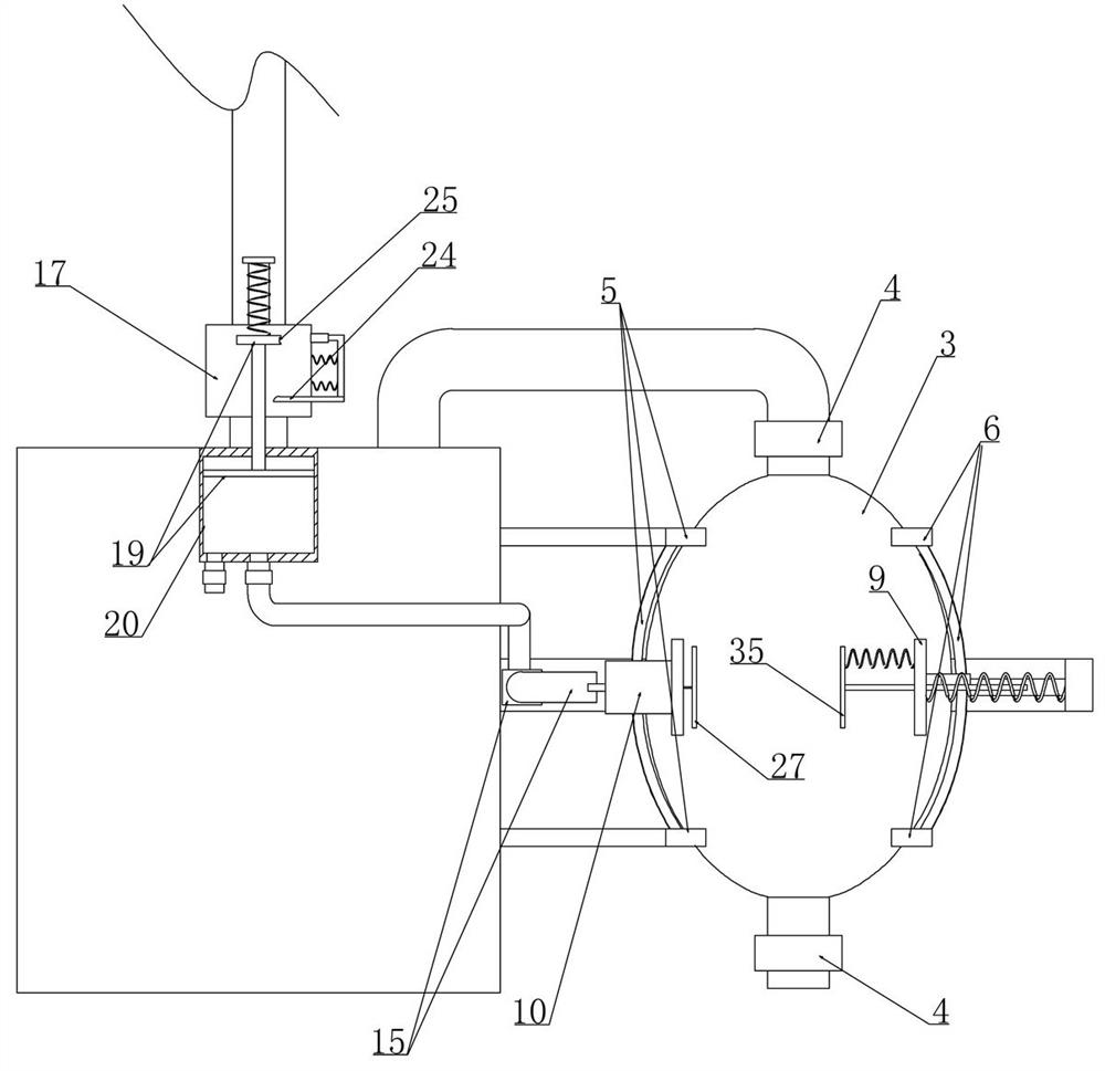
[0035] Embodiment 3, on the basis of embodiment 2, as attached figure 2 As shown, the transmission device includes a U-shaped tube 15 fixedly installed on the wall of the collection bottle 1 and the two cantilevers of the U-shaped tube 15 communicate with the outside world respectively (as attached Figure 9 , 11 As shown, the U-shaped tube 15 cantilever is provided with an opening on the side facing the cylinder 10 to realize communication with the outside world (not numbered in the figure), as attached Figure 9 As shown, the drive rod 13 is placed in the cantilever of the U-shaped tube 15, and one end is integrally provided with a valve plate 16 that is in sliding contact with the inner wall of the U-shaped tube 15 (the valve plate 16 is in close contact with the inner wall of the U-shaped tube 15 and is provided with a sealing ring to To ensure air tightness), a spring is connected between the side of the valve plate 16 facing the cylinder 10 and the U-shaped tube 15, as...


PUM


Abstract

The invention relates to a postoperative drainage device for the thyroid and breast surgery department. The problem that in the prior art, during postoperative drainage of a patient, many negative pressure machines need to be occupied or frequent manual operation of medical staff is needed is effectively solved. According to the technical scheme, the device can correspondingly control a rubber negative pressure ball to act according to changes of the negative pressure environment in a collecting bottle, so that the negative pressure environment in the collecting bottle is adjusted, and automatic adjustment of the air pressure environment in the collecting bottle is completed under the condition that a negative pressure machine and medical staff are not needed; the use of a negative pressure machine is reduced, and the complexity caused by repeated manual operation of medical staff frequently going to and out of each ward is also avoided.

Description

technical field [0001] The invention belongs to the technical field of medical devices, and in particular relates to a drainage device after nail breast surgery. Background technique [0002] After thyroid breast surgery, drainage is usually performed on the affected part of the patient. The main function is to drain the blood, fluid, and gas in the deep or shallow parts of the body. The existing drainage is usually divided into passive drainage and active drainage. Passive drainage is mainly Through the gravity of the drainage object itself or the pressure of the drainage port, it flows from a high place to a low place, and then collects the effusion in the drainage bottle, which belongs to passive drainage. Active drainage uses the negative pressure principle in physics, mainly through drainage. The negative pressure generated by the ball itself absorbs the drainage material, so as to discharge the blood and fluid from the affected area out of the human body; [0003] Pas...

Claims


Application Information

Patent Timeline
Patent Type & Authority Applications(China)
IPC IPC(8): A61M1/00
CPCA61M2205/3331
Inventor 王灿徐其锋蔡文敏赵素贞贺芳草
Owner HENAN PROVINCE HOSPITAL OF TCM THE SECOND AFFILIATED HOSPITAL OF HENAN UNIV OF TCM
Why Eureka
Try Eureka