Water turbine volute internal corner backfill grouting auxiliary structure and backfill grouting method

A backfill grouting and auxiliary structure technology, which is applied in filling, infrastructure engineering, hydropower generation, etc., can solve the problems of arranging grouting boxes and grouting pipes, poor grouting effect, and long grouting pipes, etc. Easy grouting and low grouting pressure

Pending Publication Date: 2022-04-29
POWERCHINA HUADONG ENG COPORATION LTD
View PDF0 Cites 0 Cited by
  • Summary
  • Abstract
  • Description
  • Claims
  • Application Information

AI Technical Summary

Problems solved by technology

According to the statistical analysis of the backfilling and grouting methods of the inner corners of the volutes of the recently constructed hydropower stations, especially the high-head pumped storage power stations that use volutes to maintain pressure and pour concrete, the backfilling and grouting of the inner corners of the volutes in most power stations adopts buried The grouting box is pasted on the surface of the inner corner of the volute, and is led to the turbine floor through the grouting pipe, and the grouting construction is carried out after the concrete is poured to the turbine floor. This grouting method has a long grouting pipeline, which is easy to be blocked and the grouting effect is not good; arrange the grouting There are many boxes and grouting pipes, and the construction is complicated; it is intersected with other equipment pipelines and steel bars, and there are many construction interferences

Method used


Image

  • Water turbine volute internal corner backfill grouting auxiliary structure and backfill grouting method
  • Water turbine volute internal corner backfill grouting auxiliary structure and backfill grouting method

Examples


Embodiment Construction

[0025] The present invention will be further described below in conjunction with the accompanying drawings and specific embodiments.

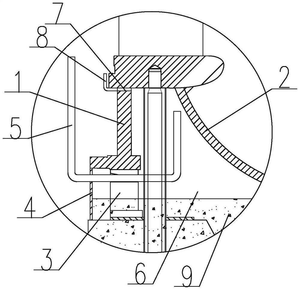
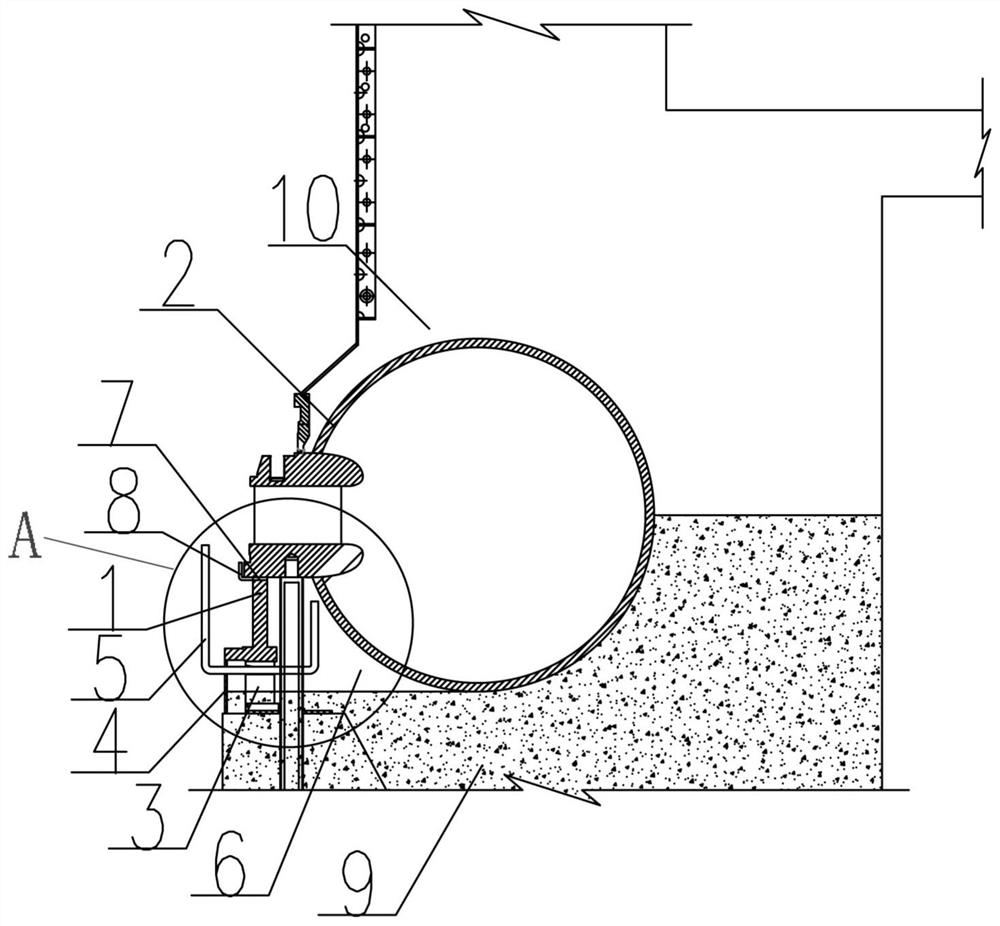
[0026] Such as figure 1 As shown, an auxiliary structure for backfilling and grouting of the inner corner of the volute of a water turbine according to the present invention is used for backfilling and grouting the inner corner of the volute 6 between the inner side of the volute 2 and the seat ring 1, and is characterized in that it includes a temporary The support seat 3, the inner formwork 4 and the grouting pipe 5, a number of temporary support seats 3 and the inner formwork 4 are arranged around the bottom of the seat ring 1, the inner formwork 4 is vertically arranged on the inner side of the temporary support seat 3, and the grouting pipe 5 extends from the inner side of the seat ring 1 through the gap between the inner template 4 and the adjacent temporary support seat 3 to the inner corner part 6 of the volute.

[0027] The inlet end ...


PUM


Abstract

The invention discloses a water turbine volute internal corner backfill grouting auxiliary structure and a backfill grouting method. The inner side of a seat ring is fully used as a construction space, arrangement of grouting pipelines is optimized, the arrangement work of the grouting pipelines is reduced, the grouting difficulty is reduced, and meanwhile the influence on other equipment pipelines, steel bars and concrete pouring construction is reduced. The structure comprises temporary supporting seats, inner side formworks and grouting pipes, the multiple temporary supporting seats and the multiple inner side formworks are arranged below a seat ring in a surrounding mode, and the inner side formworks are vertically arranged on the inner sides of the temporary supporting seats; the grouting pipe sequentially penetrates through the inner side formwork and the gap between the adjacent temporary supporting seats from the inner side of the seat ring and extends to the internal corner part of the volute. The method comprises the steps that the inner side formwork is installed on the inner side of the temporary supporting base; a hole is formed in the inner side formwork to install a grouting pipe; an exhaust pipe is upwards connected to the seat ring exhaust hole; backfill grouting is conducted on the volute internal corner part 6 through a grouting pipe; and cutting off the exposed parts of the grouting pipeline and the exhaust pipe.

Description

technical field [0001] The invention relates to backfilling and grouting technology for internal corners of hydropower stations and large pumping stations, in particular to the technical field of backfilling and grouting for internal corners of volute casings of hydraulic turbines. Background technique [0002] The volute and outsourcing concrete of most power stations need to jointly bear the internal water pressure of the volute. The pouring and compactness of the outsourcing concrete is crucial to the safety of the structure. Generally, the requirements for the backfill grouting of the inner corner of the volute and the pressure relief of the volute are: the concrete below the installation elevation needs to be poured for 28 days before the backfill grouting can be performed, and the last warehouse of the entire outsourcing concrete is poured 28 days after the concrete is poured and the volute is 7 days after the backfill grouting is completed. Can release pressure. Acco...

Claims


Application Information

Patent Timeline
Patent Type & Authority Applications(China)
IPC IPC(8): E02D15/02E02D17/18E02B9/00
CPCE02D15/02E02D17/18E02B9/00Y02E10/20
Inventor 彭强王红涛彭翔
Owner POWERCHINA HUADONG ENG COPORATION LTD
Why Eureka
Try Eureka