

Adjustable movable guide mechanism for efficient rod-changing wire-drawing feeding device
A technology of feeding device and guiding mechanism, which is applied in the direction of manufacturing tools and glass manufacturing equipment to achieve the effect of ensuring accurate positioning and improving the precision of the lower rod
Pending Publication Date: 2022-06-10
河南神玖天航新材料股份有限公司
View PDF0 Cites 0 Cited by
- Summary
- Abstract
- Description
- Claims
- Application Information
AI Technical Summary
Problems solved by technology
[0004] The purpose of the present invention is to provide an adjustable movable guide mechanism for a high-efficiency rod change wire drawing feeding device, to solve the guide positioning of the existing quartz rod in the process of lowering the rod The technical problem of inaccurate positioning of the mechanism leads to low positioning accuracy when the quartz rod is lowered
Method used
View moreImage
Smart ImageViewing Examples

Examples
Embodiment approach
Login to View More PUM
 Abstract
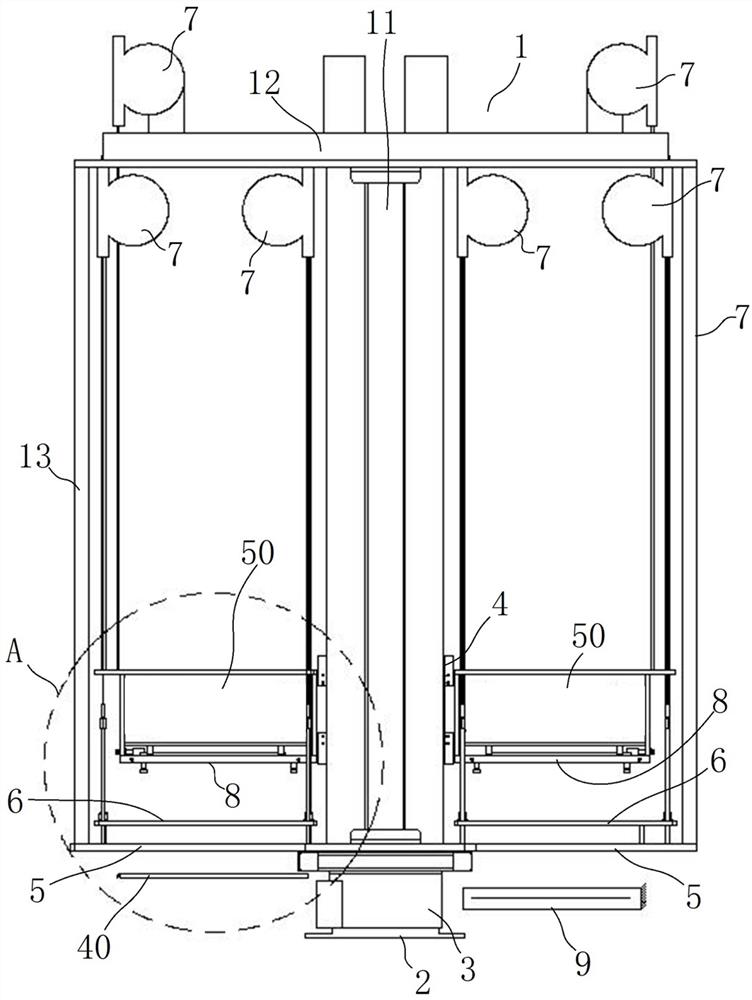
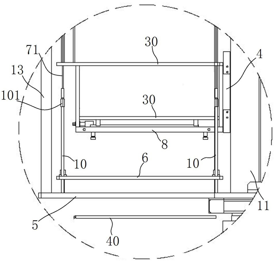
The invention relates to an adjustable movable guide mechanism for a high-efficiency rod-changing wire-drawing feeding device. The adjustable movable guide mechanism is used for solving the problem that a guide positioning mechanism is inaccurate in positioning in the quartz rod discharging process. The rod feeding mechanism comprises a rod clamping mechanism, the rod clamping mechanism forms an upper positioning structure of a quartz rod, and a plurality of first rod penetrating guide holes are formed in a lower guide plate; the lengths of the guide limiting rods are arranged in the vertical direction, the lower ends of the guide limiting rods are fixed relative to the lower guide plate, the upper ends of the guide limiting rods are provided with threaded sections, and position-adjustable limiting nuts are screwed on the threaded sections; the movable guide plate is assembled on the guide limiting rod in a guiding and sliding mode in the vertical direction, second rod penetrating guide holes corresponding to the first rod penetrating guide holes in a one-to-one mode are formed in the movable guide plate, the movable guide plate is arranged between the rod clamping mechanism and the lower guide plate, and the movable guide plate can slide between the lower guide plate and the limiting nut along the guide limiting rod; the spring balancer provides elastic force for the movable guide plate to move upwards so as to drive the movable guide plate to move towards the direction of the limiting nut.
Description
technical field [0001] The invention relates to an adjustable movable guide mechanism for a high-efficiency rod changing wire drawing feeding device. Background technique [0002] At present, the manufacturing method of quartz fiber is mainly through the first-level wire drawing method. When quartz rods are melted into quartz fibers, devices need to be used to drive multiple quartz rods through their corresponding burners to melt the quartz rods, and then pass through Drawing is used to process fine quartz fibers. In order to improve efficiency, dozens to hundreds of quartz rods need to be drawn each time. When the upper end of the quartz rod is clamped by the clamping mechanism and transported downward, the lower end of the quartz rod can be guided downward. Plate guide, but because the quartz rod is long, up to 1-2 meters, there is inevitably a certain amount of bending in the middle of the quartz rod, which will cause the position accuracy of the quartz rod to be lower th...
Claims
Login to View More Application Information
Patent Timeline
 Patent Type & AuthorityApplications(China)
IPC IPC(8): C03B37/025C03B37/07
CPCC03B37/0253
Inventor李泉涌李丽景
Owner河南神玖天航新材料股份有限公司