

Method of changing display direction of mobile telephone
A portable phone, a technology for displaying direction, applied in the direction of telephone communication, telephone structure, calling party number recording/indicating the called party number, etc.
- Summary
- Abstract
- Description
- Claims
- Application Information
AI Technical Summary
Problems solved by technology
Method used
Image

Examples
Embodiment Construction
[0015] Preferred embodiments of the present invention will be described in detail below with reference to the accompanying drawings. In describing the present invention, descriptions on relevant functions or structures known in the art will be omitted for a clear understanding of the concept of the present invention. Hereinafter, the following preferred embodiments of the present invention will be described with reference to the accompanying drawings. In the following description, well-known functions or constructions are not described in detail since they might obscure the invention in unnecessary detail.
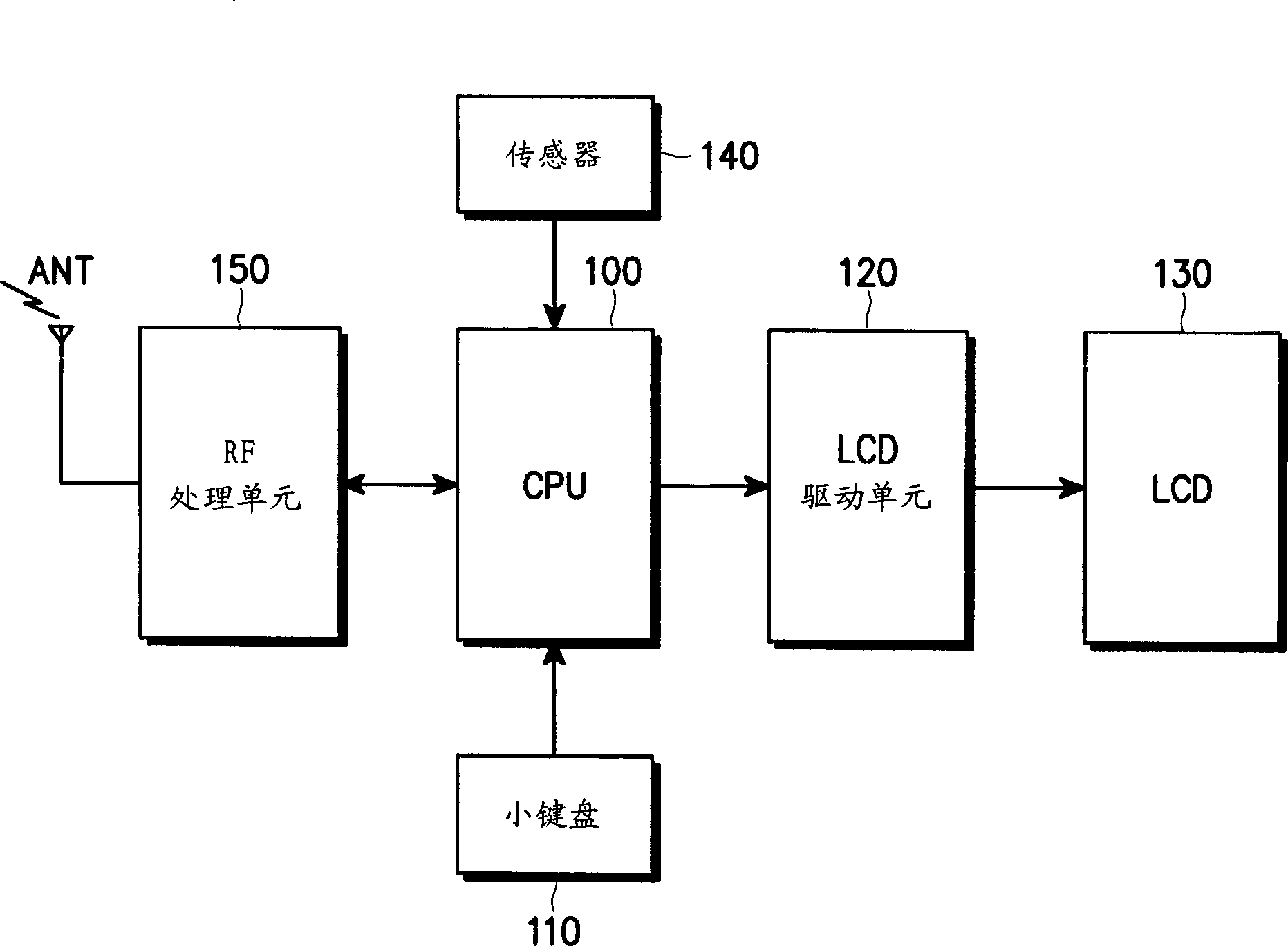
[0016] figure 1 is a block diagram illustrating the principle of controlling the display direction of an LCD in a cellular phone according to an embodiment of the present invention. refer to figure 1 , a CPU (Central Processing Unit) 100 controls the overall operation of the cellular phone. Specifically, the CPU 100 generates an LCD driving control signal for changing ...
PUM
 Abstract
Description
Claims
Application Information