Mitral valve annuloplasty ring and method

A technology of plastic surgery and mitral valve, applied in the direction of valve ring, heart valve, medical science, etc., can solve the problems that hinder the bending and movement of the heart, and the heart function cannot be optimally exerted

Inactive Publication Date: 2003-01-15
卡迪亚克·康赛普茨公司
View PDF0 Cites 15 Cited by
  • Summary
  • Abstract
  • Description
  • Claims
  • Application Information

AI Technical Summary

Problems solved by technology

This loss of flexibility prevents the normal bending and movement of the hear

Method used


Image

  • Mitral valve annuloplasty ring and method
  • Mitral valve annuloplasty ring and method
  • Mitral valve annuloplasty ring and method

Examples


Example Embodiment

[0035] The left ventricle is the main pumping chamber of the heart. Oxygenated blood from the lungs enters the left atrium and passes through the mitral valve into the left ventricle. Blood is pumped from the left ventricle to the rest of the body.
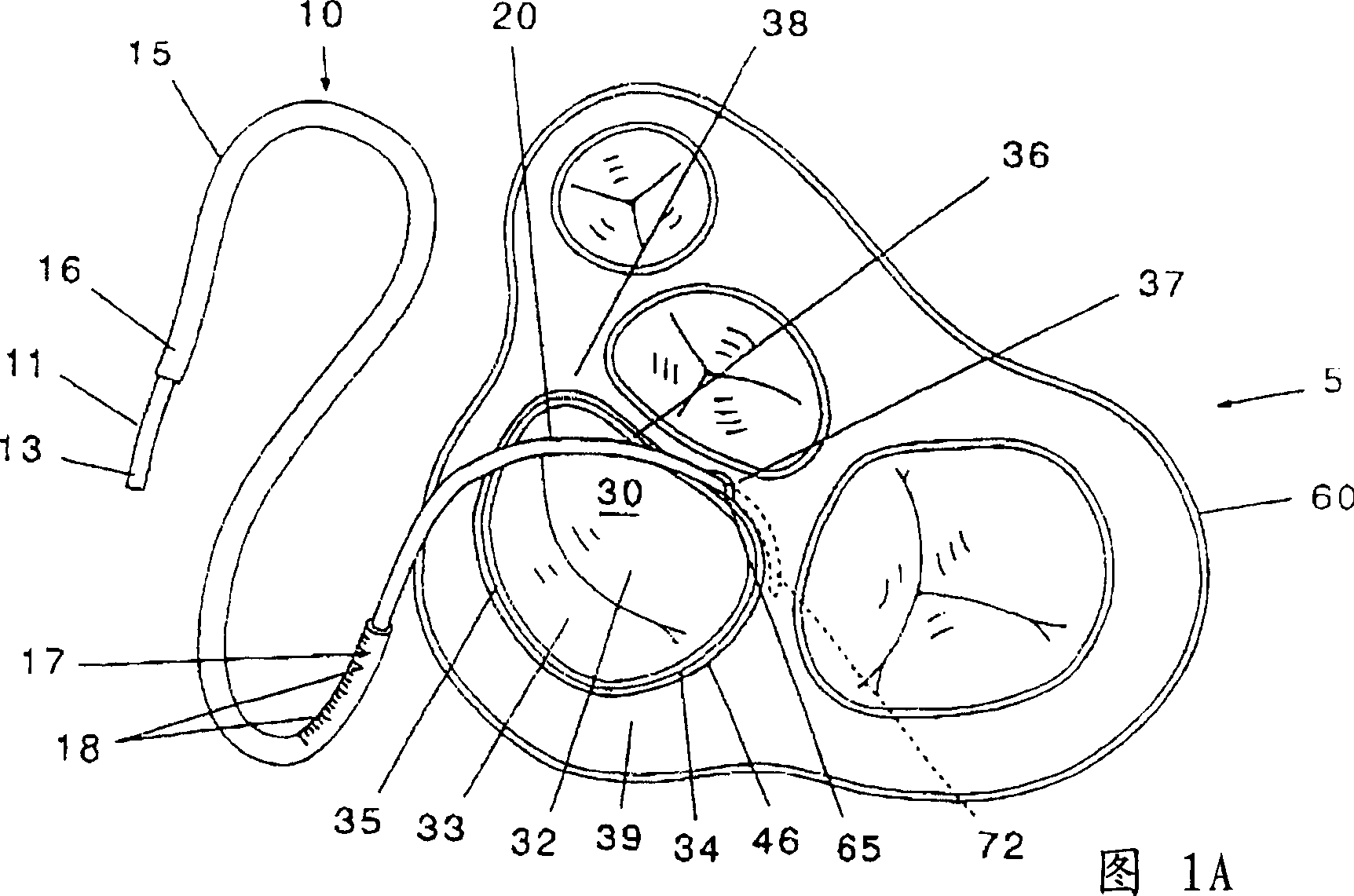
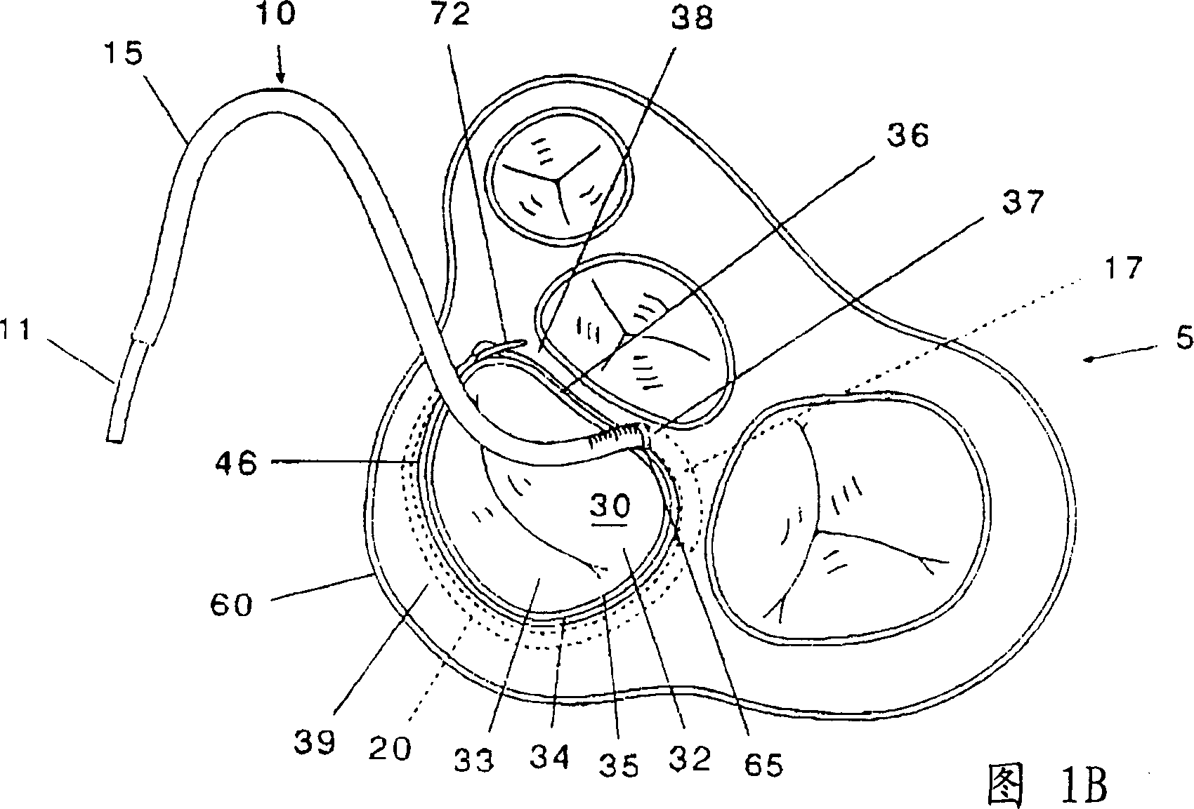
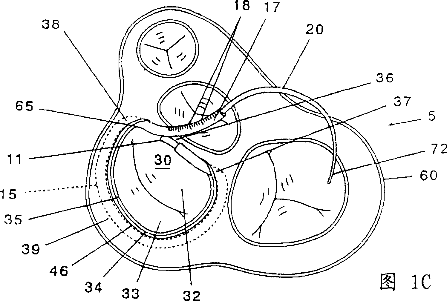
[0036] As shown in FIGS. 1A-1F, the mitral valve 30 is a one-way passive valve including a pair of leaflets, including a larger anterior leaf 32 and a smaller posterior leaf 33. The leaflets open and close according to the pressure difference in the heart 5 on each side of the mitral valve 30. The base of each anterior leaflet 32 ​​and posterior leaflet 33 is connected to the mitral valve annulus 34.

[0037] The contour of the mitral valve annulus 34 refers to the shape or form of the valve annulus 34 viewed on the general plane of the valve annulus 34. The shape of the valve annulus 34 is the shape seen from the mitral valve annulus 34 from the atrial side of the mitral valve 30 and downward.

[0038] The mitral valve annulus 34 inc...


PUM


Abstract

A mitral valve annuloplasty ring and method for implanting a mitral valve annuloplasty ring to treat mitral insufficiency by reestablishing the normal shape and contour of the mitral valve annulus. The annuloplasty ring is flexible and can be readily adjusted to different sizes and shapes. The method substantially eliminates scarring subsequent to the annuloplasty procedure to maintain flexibility of the ring and the annulus indefinitely.

Description

technical field [0001] The present invention relates to a mitral valve annuloplasty ring and a method for implanting the mitral valve annuloplasty ring to treat mitral valve insufficiency in a patient. Mitral insufficiency, also known as mitral regurgitation, is a common heart abnormality in which the heart's mitral valve does not close properly. Background technique [0002] In a properly functioning heart, when the left ventricle is in diastole, oxygenated blood flows from the left atrium through the open mitral valve into the left ventricle. When the left ventricle contracts, blood is pushed out of the left ventricle, thereby closing the mitral valve to prevent blood from flowing back or back into the left atrium. Oxygenated blood is pumped out of the heart from the left ventricle and directed into the rest of the body. [0003] With mitral insufficiency, the mitral valve doesn't close completely, and when the left ventricle contracts, some of ...

Claims


Application Information

Patent Timeline
IPC IPC(8): A61B17/06A61F2/24
CPCA61F2/2448Y10S623/904
Inventor 詹姆斯·L·考克斯
Owner 卡迪亚克·康赛普茨公司
Why Eureka
Try Eureka