

Improved heat transfer tube with grooved inner surface
An inner surface and outer surface technology used in the field of heat transfer tubes
- Summary
- Abstract
- Description
- Claims
- Application Information
AI Technical Summary
Problems solved by technology
Method used
Image

Examples
Embodiment Construction
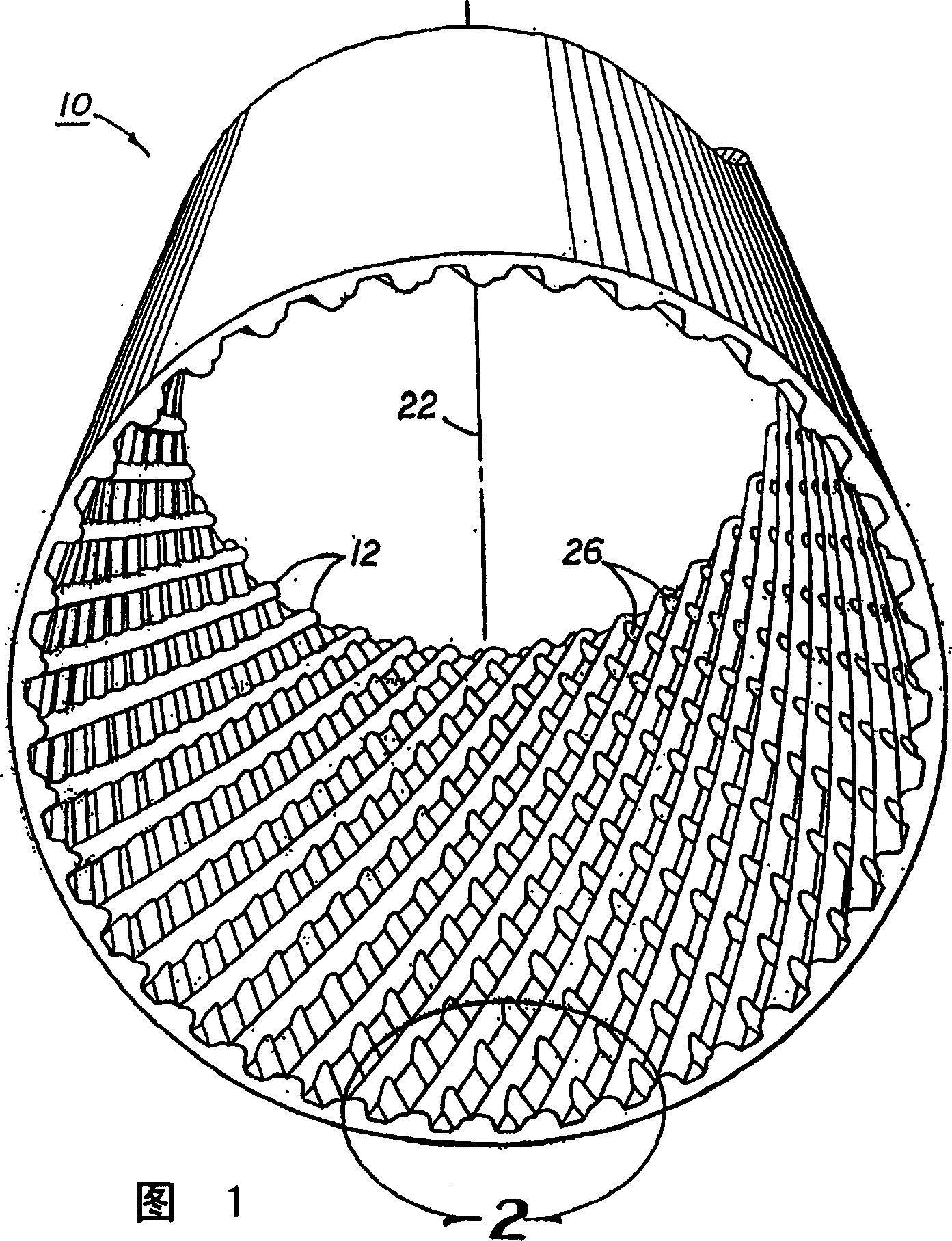
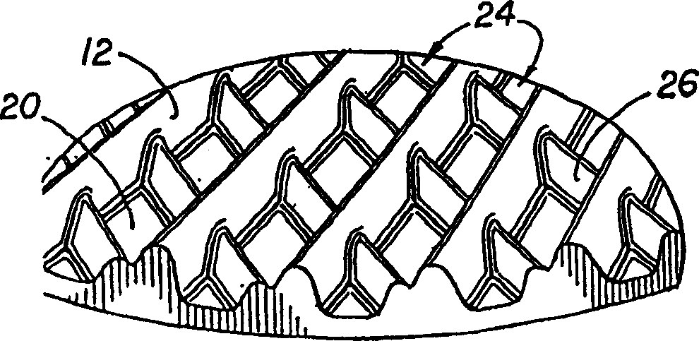
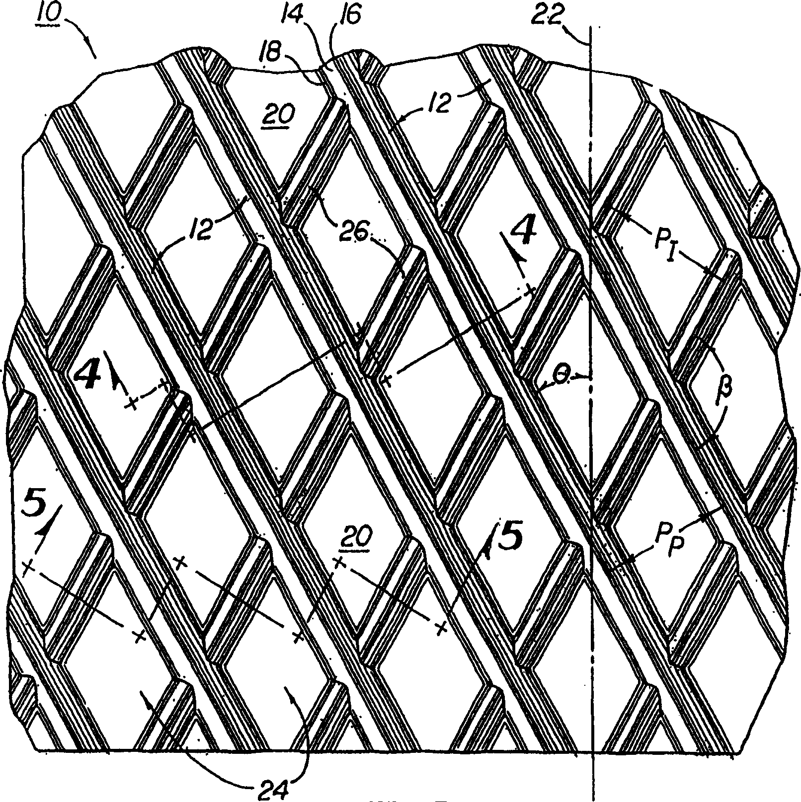
[0053] Similar to prior art patterns, one embodiment of the inner surface pattern of the tube 10 of the present invention is shown in FIGS. The cross-sectional shape of the basic fin 12 can be assumed as Figure 6-11 Any shape disclosed, but preferably a triangular shape with sloped straight sides 14, rounded apex 16, and rounded edge 18 at the junction of straight side 14 and inner surface 20 of tube 10 (see Figure 4 ). Basic fin height H p It can vary depending on the diameter of the tube 10 and the particular application, but is preferably between 0.004-0.02 inches. like image 3 As shown, the base fins 12 may be positioned at a base fin angle Θ relative to the longitudinal axis 22 of the tube 10, the angle being between 0°-90°. The angle θ is preferably between 5°-50°, more preferably between 5°-30°. Finally, the number of elementary fins 12 positioned along the inner surface 20 of the tube 10, and the pitch P of the elementary fins p (determined as the distance mea...
PUM
 Abstract
Description
Claims
Application Information