Controlled cooling method after H-shape steel rolling

A technology for controlled cooling and H-beams, applied in metal rolling, metal rolling, manufacturing tools, etc., can solve the problems of inability to meet users, uneven microstructure of cross-section, and unattainable comprehensive mechanical properties and overall service performance of H-beams. , to achieve the effect of enhancing competitiveness, improving comprehensive mechanical properties, and improving mechanical properties

Inactive Publication Date: 2005-02-23
NORTHEASTERN UNIV
View PDF0 Cites 14 Cited by
  • Summary
  • Abstract
  • Description
  • Claims
  • Application Information

AI Technical Summary

Problems solved by technology

Therefore, during the rolling and cooling process of the H-beam, the entire section often has an uneven structure state, and finally the compreh

Method used


Image

  • Controlled cooling method after H-shape steel rolling
  • Controlled cooling method after H-shape steel rolling

Examples


Embodiment

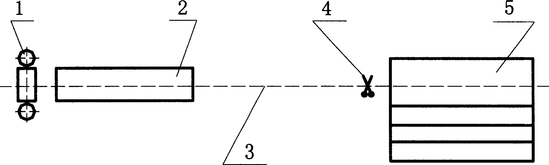
[0016] A set of controlled cooling device is installed behind the H-beam universal rolling mill in a certain factory. The layout of the cooling system is as follows figure 1 As shown, the cooling device adopts the air mist cooling method. The size of the billet used for the rolled H-beam is 300mm×200mm rectangular billet, and the finished size of the H-beam is HM200×150. The billet is first rolled for 5 passes in the two-roll billet mill, then rolled for 3 passes in the universal rough rolling mill unit in the form of UEU, and finally rolled once in the universal finishing mill.

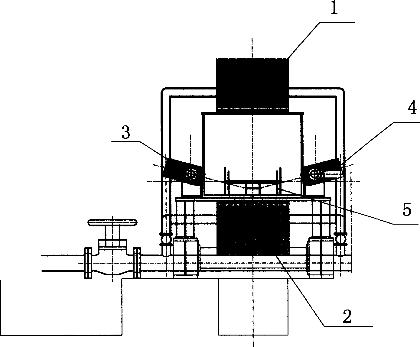
[0017] After the H-shaped steel is rolled, it enters the control cooling device for cooling. The cross-sectional layout of the nozzle in the cooling device is as follows: figure 2 As shown, the upper and lower groups of nozzles are arranged along the vertical direction of the H-shaped steel axis, and the nozzles on both sides form an included angle of about 20°C along the horizontal axis of the H-s...


PUM


Abstract

A controlled cooling method for the rolled H-shaped steel features that the just rolled H-shaped steel is cooled by the aerosolizing mode in a controllable cooler and its cooling speed is more than 50 deg.C/s.

Description

Technical field [0001] According to the International Patent Classification Table, the invention belongs to the technical field of production control and cooling of high-performance H-shaped steel for structures. technical background [0002] H-beam is an ideal economical cross-section profile. Compared with ordinary I-beam, it has the advantages of light weight, better performance, more specifications, economical and reasonable section, convenient use and saving metal materials. It is widely used in high-rise buildings, machinery manufacturing, Large-scale factory buildings, power station construction, airports, port terminals, tunnels, underground railways, bridges, ships, transport vehicles, highways, tunnel support engineering, offshore oil platforms, simple garages, seaside holiday houses and various engineering structural parts, etc. [0003] H-shaped steel has the advantages of parallel inner surfaces of two legs, right-angled ends of two legs, reasonable metal distri...

Claims


Application Information

Patent Timeline
IPC IPC(8): B21B1/10B21B45/02
Inventor 吴迪赵宪明王国栋刘相华王黎筠岳发
Owner NORTHEASTERN UNIV
Why Eureka
Try Eureka