

Iron with foam moistening means
A technology of heating device and foaming device, which can be applied to hand irons, washing devices, household appliances, etc., and can solve the problem of unsatisfactory moisture
- Summary
- Abstract
- Description
- Claims
- Application Information
AI Technical Summary
Problems solved by technology
Method used
Image

Examples
Embodiment Construction
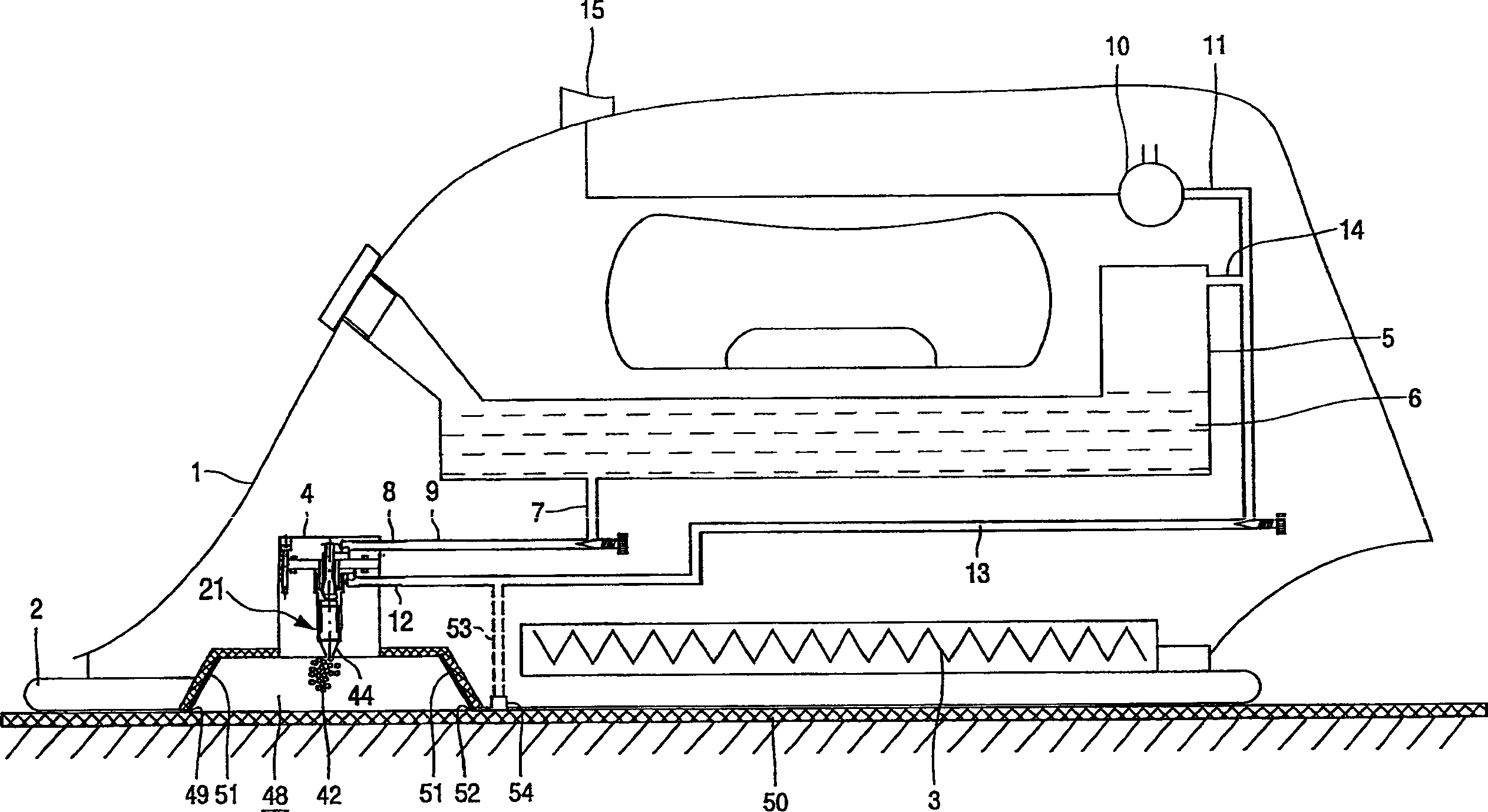
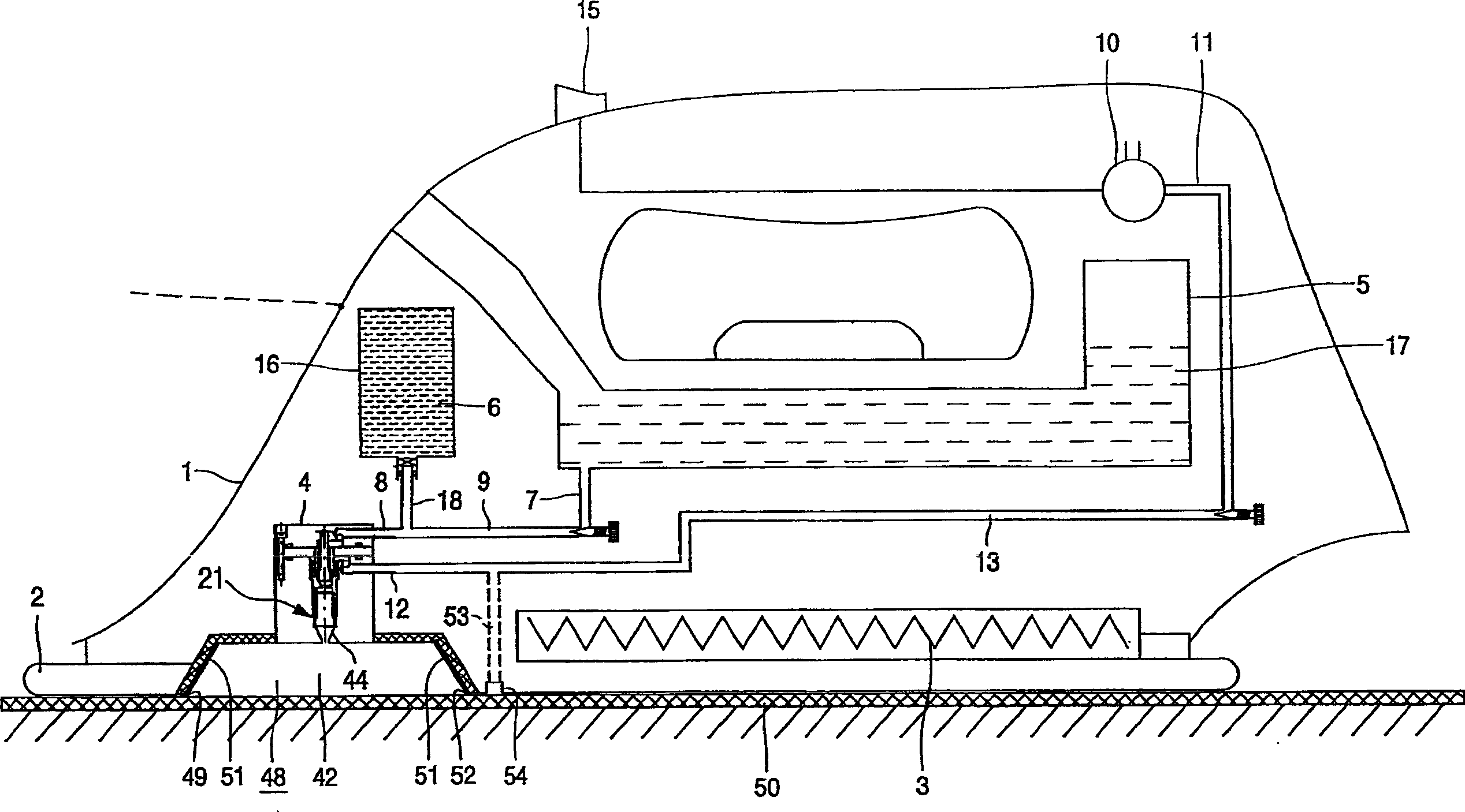
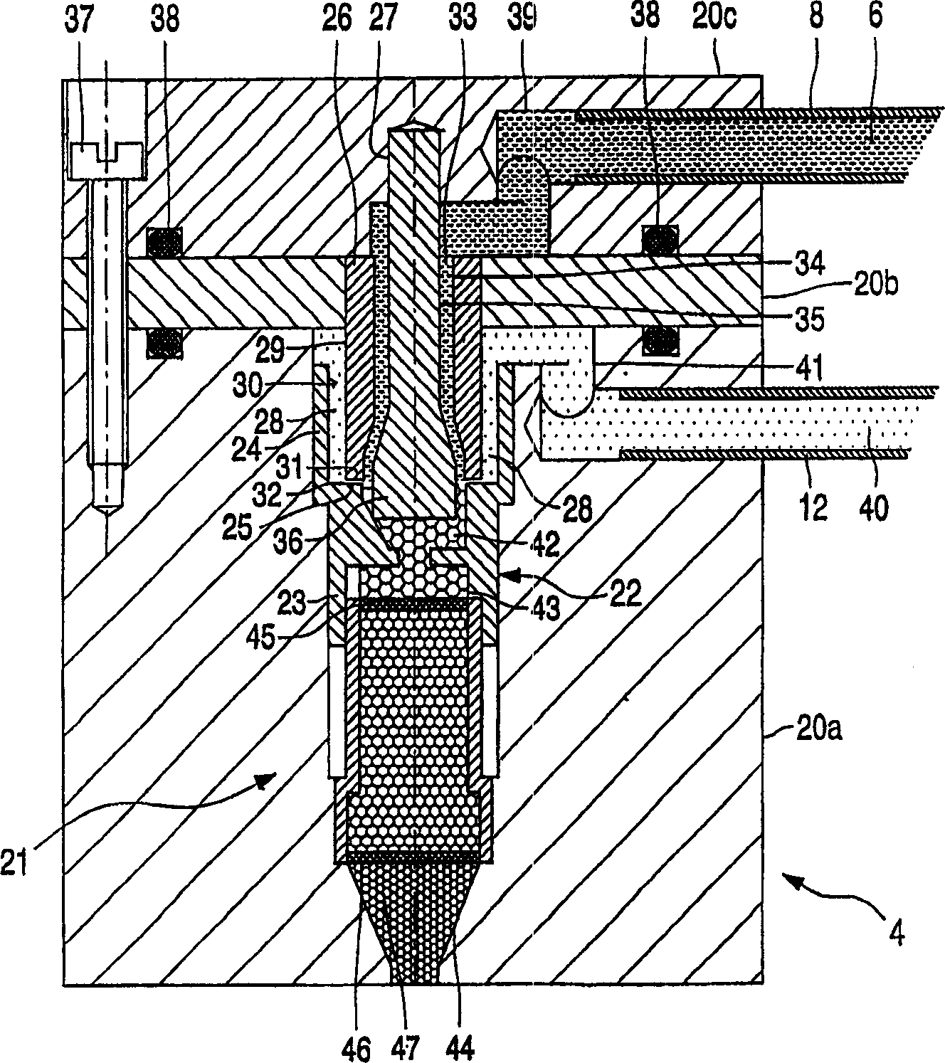
[0023] exist figure 1 In the first embodiment shown, the iron comprises a housing 1 with a soleplate 2 heated by means of an electric heating element 3 . The foam is generated by the nozzle unit 4, the work of which will be referred to below figure 2 illustrate. The iron comprises a reservoir 5 containing a foaming liquid 6 under pressure. The storage tank 5 may be, for example, a detachable cassette. Foaming liquids contain a small amount of surfactant in order to lower surface tension. The concentration of surfactant must be only above the critical micelle concentration (CMC) in order to generate foam. In practice, this means a concentration of about 0.2-0.5 weight percent. The reservoir 5 has an outlet 7 connected by a conduit 9 to a first inlet 8 of the nozzle unit 4 . The flow rate of the foaming liquid from the reservoir to the nozzle unit can be adjusted if desired. The iron also comprises an electric air pump 10 , the outlet 11 of which is connected to a second...
PUM
 Abstract
Description
Claims
Application Information