Magneto generator

A permanent magnet generator and permanent magnet technology, which is applied to synchronous motors with stationary armatures and rotating magnets, synchronous machines, electrical components, etc. And other issues

Inactive Publication Date: 2005-04-27
FUJI CERA TECH
View PDF5 Cites 8 Cited by
  • Summary
  • Abstract
  • Description
  • Claims
  • Application Information

AI Technical Summary

Problems solved by technology

First, since there is a gap between the permanent magnet member and the flux control ring, a holding tube of non-magnetic material such as SUS304 installed to fix the permanent magnet to the rotor, there is a gap, which becomes a magnetic field for the magnetic circuit path. The resistance increases, and the magnetic flux density decreases significantly
Second, regardless of the magnetic flux of the permanent magnet, it is necessary to increase the number of coils required to obtain a high power generation voltage that can be generated by the magnetic force, but the space for storing the coils is small.
Fifth, in order to perform flux c

Method used


Image

  • Magneto generator
  • Magneto generator
  • Magneto generator

Examples


Embodiment Construction

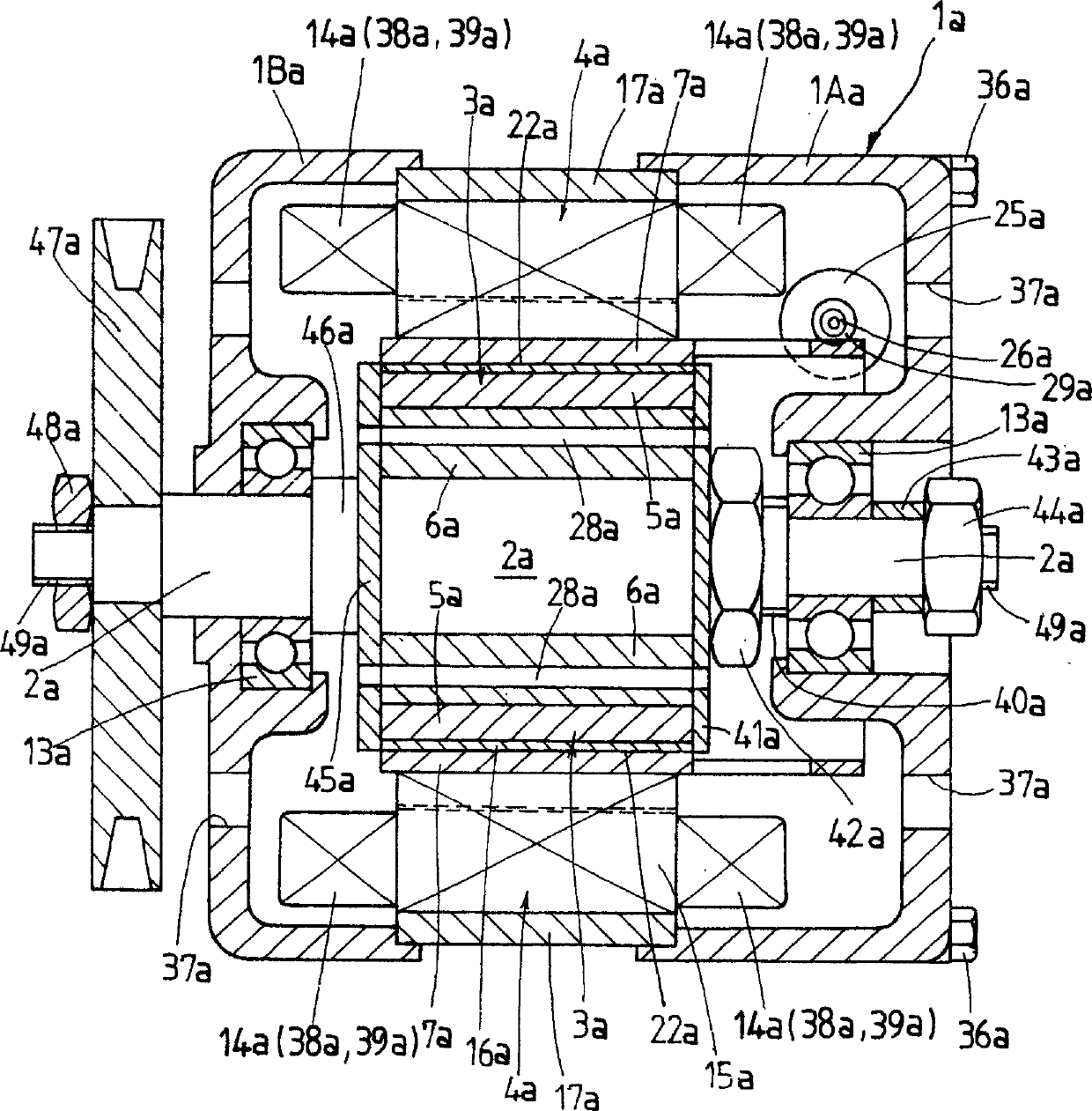
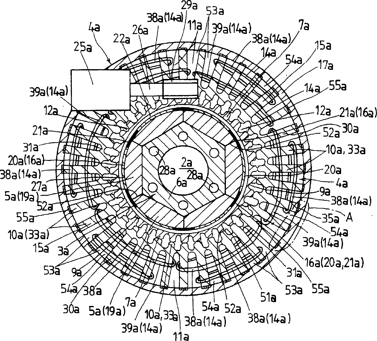
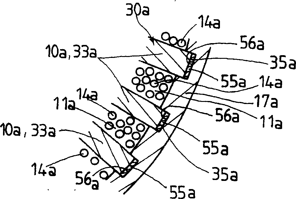
[0073] Next, the first to fourth embodiments of the permanent magnet generator according to the present invention will be described with reference to the accompanying drawings. In the first embodiment to the fourth embodiment, the same terms are used for components having the same function, and in each embodiment, even if the same term is used, the symbols are different. In the first embodiment, the symbols Add a suffix a to the top, add a suffix b in the second embodiment, add a suffix c in the third embodiment, and append a suffix d in the fourth embodiment, and omit its repetition for the same structure illustrate.

[0074] First, with reference to FIGS. 1 to 5, the first embodiment of the permanent magnet generator according to the present invention will be described. In the first embodiment, the mounting body referred to in the present invention is constituted by a casing 1a.

[0075] Such a permanent magnet generator is provided with a magnetic flux control ring 7a for...


PUM


Abstract

A permanent-mannet generator, setting a pectination front end part on a stator and a pectination teeth part on a magnetic flux control loop locating opposite with the stator. To make the magnetic flux control loop rotate and swing, and to change area of the pectination teeth part opposite to the pectination front end part, and to restrain magnetic flux through the magnetic circuit as well as to generate electric power of constant voltage. Forming chamfering edges parts on two turning parts in cycle direction of the pectination teeth part and the pectination front end part, so as to form gap of magnetic flux interspace with accuracy.

Description

technical field [0001] The invention relates to a permanent magnet generator, which comprises a rotor with permanent magnets, a stator disposed opposite to the rotor, and a magnetic flux control ring that is rotatably arranged relative to the stator to control magnetic flux. Background technique [0002] In the prior art, since permanent magnets are used for the rotor, a large power generation can be obtained with a simple structure. In recent years, systems incorporating such generators have been used as generators for automobiles, wind power generators, etc. There are more and more phenomena. A permanent magnet generator, for example, can fully perform its function even if the voltage changes when sending the generated electric power to the motor, but it is necessary to adjust the voltage when matching this electric power with the battery voltage of all devices that drive the car. Variations coincide with constant voltage operation. In permanent magnet generators, in ord...

Claims


Application Information

Patent Timeline
IPC IPC(8): H02K21/00H02K21/12
Inventor 河村英男深尾正加茂坂光伸
Owner FUJI CERA TECH
Why Eureka
Try Eureka