Tunnel lighting lamp for reducing strobe

A lamp and tunnel technology, applied in the patented tunnel lighting field, can solve the problems of reducing stroboscopic, affecting driving safety, distraction, etc., and achieving the effect of avoiding stroboscopic and reducing stroboscopic

Inactive Publication Date: 2005-10-05
DONGSHENG ELECTRONICS SHANGHAI
View PDF0 Cites 1 Cited by
  • Summary
  • Abstract
  • Description
  • Claims
  • Application Information

AI Technical Summary

Problems solved by technology

Strobe will bring excessive stimulation to the driver, cause distraction and annoyance, and seriously affect driving safety
[0003] Up to now, in order to reduce the stroboscopic effect, foreign countries have adopted the method of adjusting the arrangement interval of lamps, that is, according to the specified speed of the tunnel, the interval between lamps is controlled at less than 2.5PPS or greater than 12.5PPS (PPS is light per second. In the range of number of pulses), there is no example of changing the light distribution of lamps to reduce strobe. and de Boer & Van Bommel "Roadlighting" 1980)

Method used


Image

  • Tunnel lighting lamp for reducing strobe
  • Tunnel lighting lamp for reducing strobe

Examples


Embodiment Construction

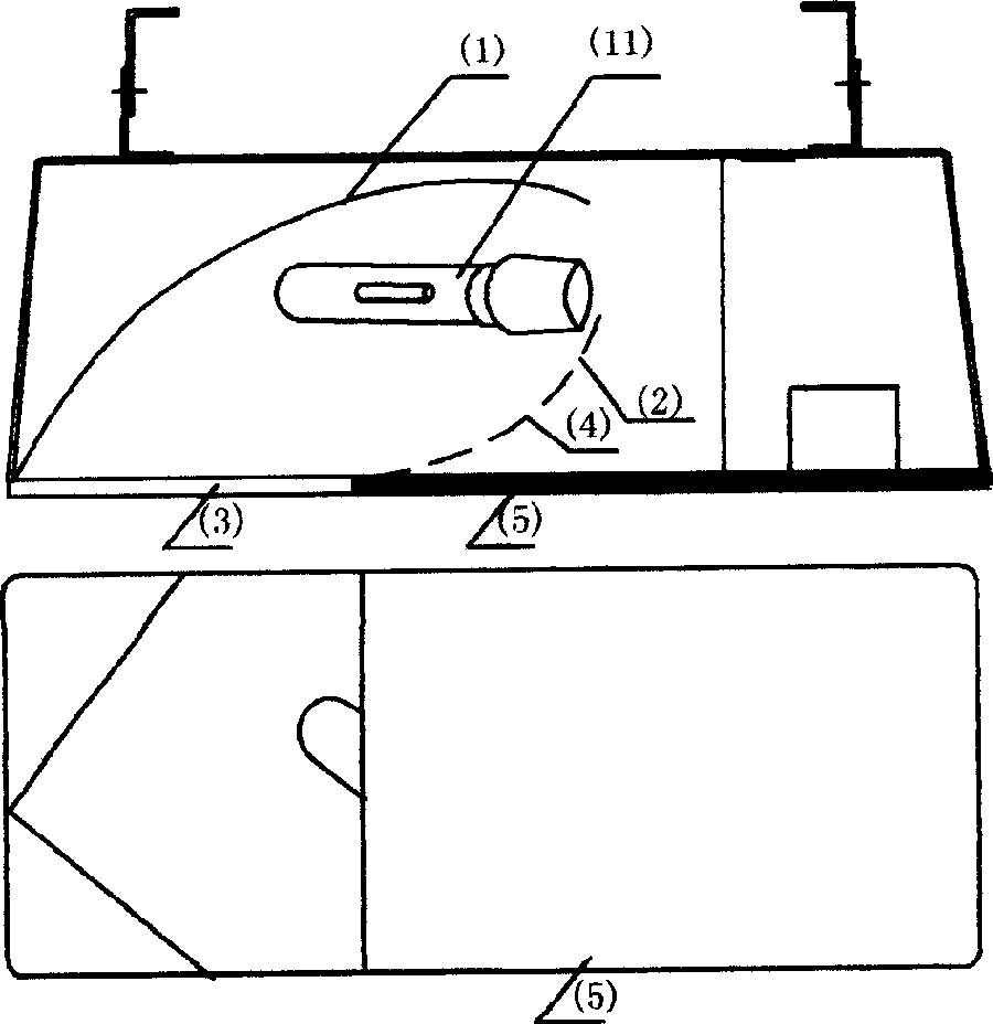
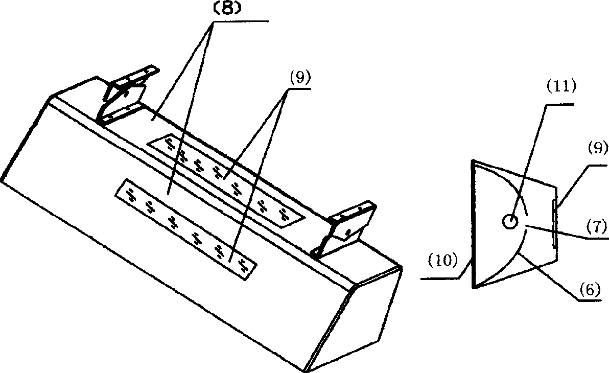
[0008] exist figure 1 Among them, the light source (11) is in a horizontal and slightly deflected state, cooperates with the built-in asymmetric reflector (1) (2) to emit asymmetrical light, and has some diffusion angle and light speed shape through the protective glass (3), illuminating the road ahead .The backward light comes from the translucent or prism light-transmitting cover (5) in front of the lamp, and part of the light from the light source leaks from the reflector (2) onto the prism glass (5), which acts as a visual guide, horizontally The diffusion angle is consistent with the width of the tunnel, about 60°; the vertical diffusion angle is about 45°, projecting on the road ahead of the traffic on the road. The lowermost part of the down-ray from the reflected beam to the road surface is cut off by the glass surface (5) of the lamp, and the cut-off light shape with the cut-off angle at the lower end is the same as that of the windshield of the car. Rarely, the cut-...


PUM


Abstract

The present invention pertains to a tunnel lighting technology, which is object to reduce the stroboscopic the driver generates to the traditional lighting means and lights in the moveing vehicles in an one-way tunnel. The present invention designs two new lamps, one lamp installed along the location of the traditional lights collocation, the second lamp installed on the roof surface of the tunnel. The lights irradiated by both lamps have a rear cut-off angle designed based on the installation angle of the car windshieldsed, thereby reducing the stroboscopic; and at the same time the lamps all have a shining surface with a certain brightness which sends the light backwards, which alows the driver in the moving vehicles to understand the direction of the front road, playing a guiding role.

Description

technical field [0001] The patent of the invention belongs to the technical field of tunnel lighting, and the purpose is to reduce the stroboscopic flicker produced by drivers in vehicles traveling in a one-way tunnel to traditional lighting methods and lamps. Background technique [0002] Traditional tunnel lighting uses square lamps with a built-in cylindrical symmetrical or asymmetrical reflector. The light source is placed horizontally and emits left and right symmetrical beams. These lamps are installed on both sides above the tunnel one by one at intervals. The light projected forward illuminates the road surface without causing stroboscopic flicker to the driver, while the light projected backward serves as a visual guide in addition to producing light spots in the eyes of the driver. In addition, a lot of light is projected on the driver's platform and the hood, and its reflection and the distance between lamps and lanterns together form reflections that change at a ...

Claims


Application Information

Patent Timeline
Patent Type & Authority Applications(China)
IPC IPC(8): F21S8/00F21V13/00F21W131/10
Inventor 章海骢范毅杨骏
Owner DONGSHENG ELECTRONICS SHANGHAI
Why Eureka
Try Eureka