Camera stroboflash prevention device

An anti-camera and stroboscopic technology, applied in camera, exposure control, optics, etc., can solve the problems of unavoidable stroboscopic, camera stroboscopic, changing light source environment, etc., to avoid camera stroboscopic, reduce size, work station compact effect

Pending Publication Date: 2021-10-01
珠海视熙科技有限公司
View PDF0 Cites 0 Cited by
  • Summary
  • Abstract
  • Description
  • Claims
  • Application Information

AI Technical Summary

Problems solved by technology

[0004] CMOS image sensors are widely used in mobile phones, computers, smart TVs, digital conference equipment, security equipment, vehicle equipment, medical equipment, military equipment, and aviation equipment. Most of these CMOS image sensors use rolling progressive exposure methods ;In most environments, lighting fixtures powered by AC power are often used, such as incandescent lamps and some fluorescent lamps. When the camera is shooting or videoing in this light source environment, it is very easy to have camera flicker, which seriously affects the image quality and has a very poor quality. user experience
[0005] The existing technology generally adopts the following strategies to solve the problem of camera flicker: the first solution is to change the light source environment: for example, draw the curtains to make the camera measure light in the dark, turn off the light source that causes strobe or replace the light device that causes strobe ; But this method requires user intervention, the experience is not good, and the user may not even accept it
The second solution is to change the camera module model: different camera module sensor parameters have certain differences, and the probability of stroboscopic occurrence in some scenes is also different, so in theory, you can choose the one with a lower stroboscopic probability However, changing the sensor model means that the manufacturer needs to change the design plan, cost plan, and even sacrifice the excellent characteristics of the original sensor; and the scene of strobe flicker after replacement is relatively rare, but it cannot be avoided fundamentally strobe
The third solution is to adjust the camera sensor exposure parameters from the software: for example, set the exposure time to an integer multiple of 1 / 100s (the corresponding AC power supply is 50Hz) or increase EV until the stroboscopic disappears; this method can eliminate the stroboscopic But it will cause the picture to be overexposed
However, people generally use an electronic ND mirror (electronic ND mirror) or a variable aperture to reduce the amount of incoming light at the front of the camera lens. However, the electronic ND mirror is generally used in high-end professional camera equipment, and the cost is extremely high, so it is not easy to popularize; limited by cost and Due to size restrictions, it is difficult to add variable apertures to camera modules of mobile phones, computers, etc. A small aperture is an ordinary aperture, which cannot avoid flickering)

Method used


Image

  • Camera stroboflash prevention device
  • Camera stroboflash prevention device
  • Camera stroboflash prevention device

Examples


Embodiment 1

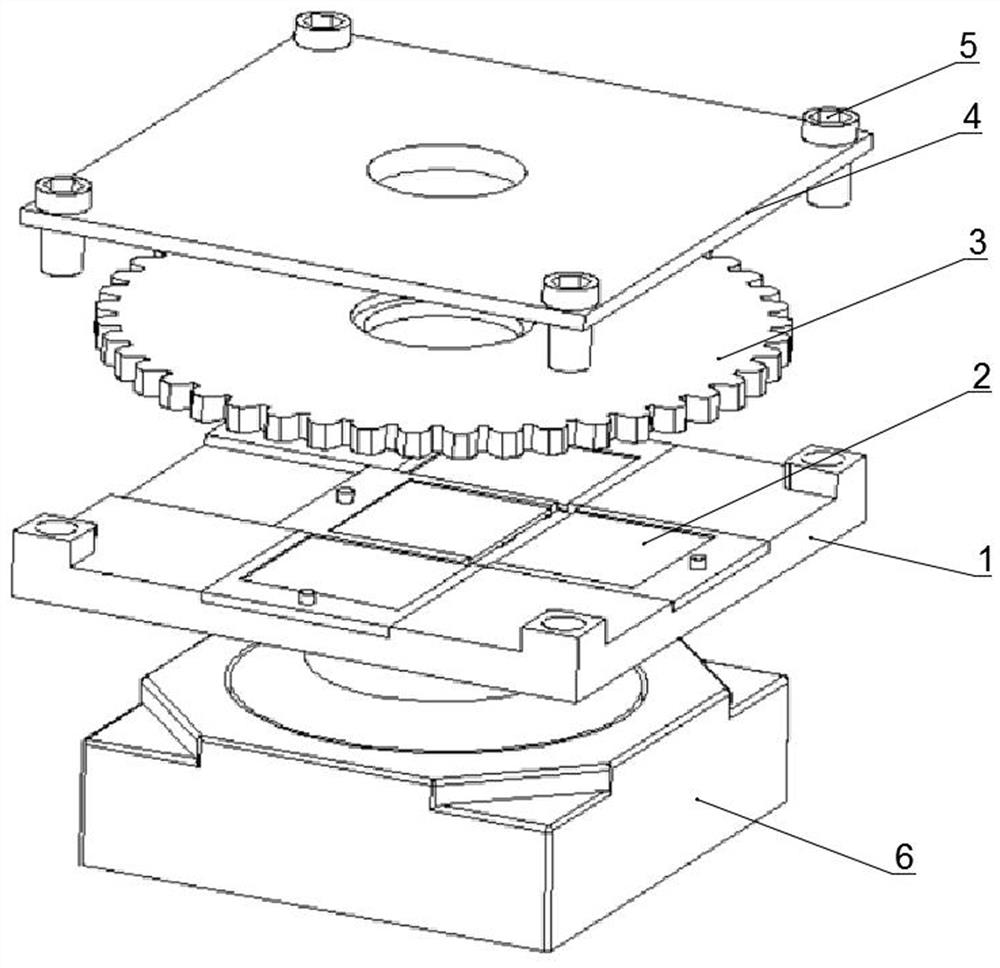
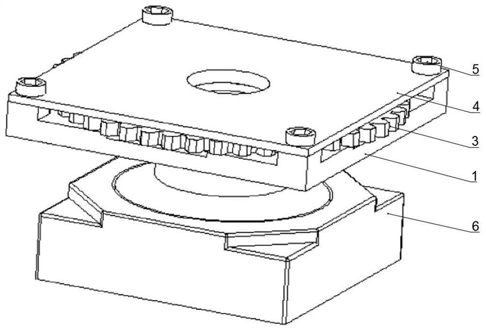
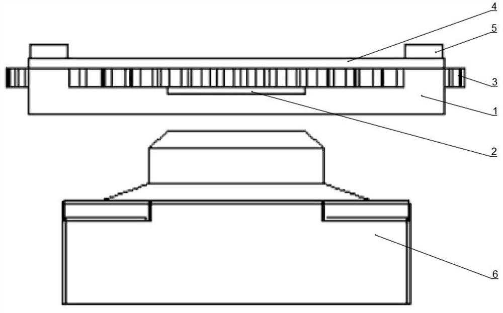
[0039] An anti-camera strobe device such as Figure 1-Figure 7As shown, including light reduction film module and motion mechanism. The anti-camera stroboscopic device is fixed in front of or directly above the lens of the camera module 6, the camera module 6 and the light reduction film module are connected to the MCU, and the movement mechanism is controlled by the MCU, which can push the light reduction film assembly 2 to slide. The light-reducing film module includes a guide rail plate 1 and a light-reducing film assembly 2, and the light-reducing film assembly 2 is slidably matched with the guide rail plate. The light reduction film module is located below the moving mechanism, close to the camera module 6, and there is a certain gap between the bottom of the light reduction film module (that is, the bottom of the guide rail plate) and the lens of the camera module 6. When reaching the farthest point, the outer edge of the lens is not in contact with the light reduction ...

Embodiment 2

[0056] An anti-camera stroboscopic device, the difference from Embodiment 1 is that the guide groove is in the shape of a line, and there are 3 moving stations, including 2 fixed stations and a central station at both ends; the guide groove There are two groups of light-reducing film assemblies 2 inside, and the length of the guide groove is three times the length of the light-reducing film assembly; the curve C of the drive groove 7 of the wheel disc 3 consists of a large arc of more than 3 / 4 and a free curve that is concave Composition, the difference between the furthest distance and the shortest distance from the center point of the curve C is just equal to the travel range of each light-reducing film assembly 2 . All the other parts are the same as in Example 1.


PUM


Abstract

The invention belongs to the technical field of camera stroboflash prevention, and discloses a camera stroboflash prevention device which is arranged in front of a lens of a camera module and comprises a light reducing piece module, a movement mechanism is connected to the light reducing piece module, and multiple groups of light reducing piece assemblies are arranged in the light reducing piece module in a sliding mode. Coaxial light holes are formed in the light reducing piece module and the movement mechanism, the light reducing piece module comprises a guide rail plate and a light reducing piece assembly, a guide groove is formed in the guide rail plate, the light reducing piece assembly is arranged in the guide groove, and the movement mechanism drives the light reducing piece assembly to slide in the guide groove. According to the device provided by the invention, camera stroboflash can be avoided, the picture brightness is relatively natural, the camera stroboflash can be avoided, the picture effect can be considered in different scenes, and overexposure cannot be generated. Meanwhile, the device is compact in structure, small in size, simple in structure and suitable for being widely applied to camera modules in the fields of mobile phones, computers, intelligent television equipment, digital conference equipment and the like.

Description

technical field [0001] The invention relates to the technical field of anti-camera flickering, in particular to an anti-camera flickering device. Background technique [0002] Camera strobe, also called power frequency flicker, power line flicker, English Power-line flicker. Camera flicker is a common physical phenomenon when the camera is shooting or video recording under the electric light source environment. [0003] Since the frequency of alternating current in my country is 50Hz, and the frequency of alternating current in countries such as Britain and the United States is 60Hz, the corresponding energy change frequencies are 100Hz and 120Hz respectively. Incandescent lamps and some fluorescent lamps will flicker brightly and darkly at the corresponding frequency of alternating current energy changes during the working process, but because the flickering frequency exceeds the perception range of the human eye, this kind of flickering cannot be directly perceived by peo...

Claims


Application Information

Patent Timeline
Patent Type & Authority Applications(China)
IPC IPC(8): G03B7/18
CPCG03B7/18
Inventor 肖兵黄昌松
Owner 珠海视熙科技有限公司
Why Eureka
Try Eureka