Electronic ballast and operating method

An electronic ballast and circuit technology, applied in the direction of electric light sources, electrical components, lighting devices, etc., can solve problems that are not conducive to the protection of users' eyesight, and achieve the effects of constant luminous brightness, low heat generation, and high input impedance

Inactive Publication Date: 2009-08-19
江苏威科变压器有限公司 +1
View PDF7 Cites 0 Cited by
  • Summary
  • Abstract
  • Description
  • Claims
  • Application Information

AI Technical Summary

Problems solved by technology

When the above-mentioned electronic ballasts are applied to fluorescent lamps or HID lamps, the brightness of the lamps still changes with the fluctuation of the grid voltage, which is not conducive to the protection of users' eyesight.

Method used


Image

  • Electronic ballast and operating method
  • Electronic ballast and operating method
  • Electronic ballast and operating method

Examples


Embodiment 1

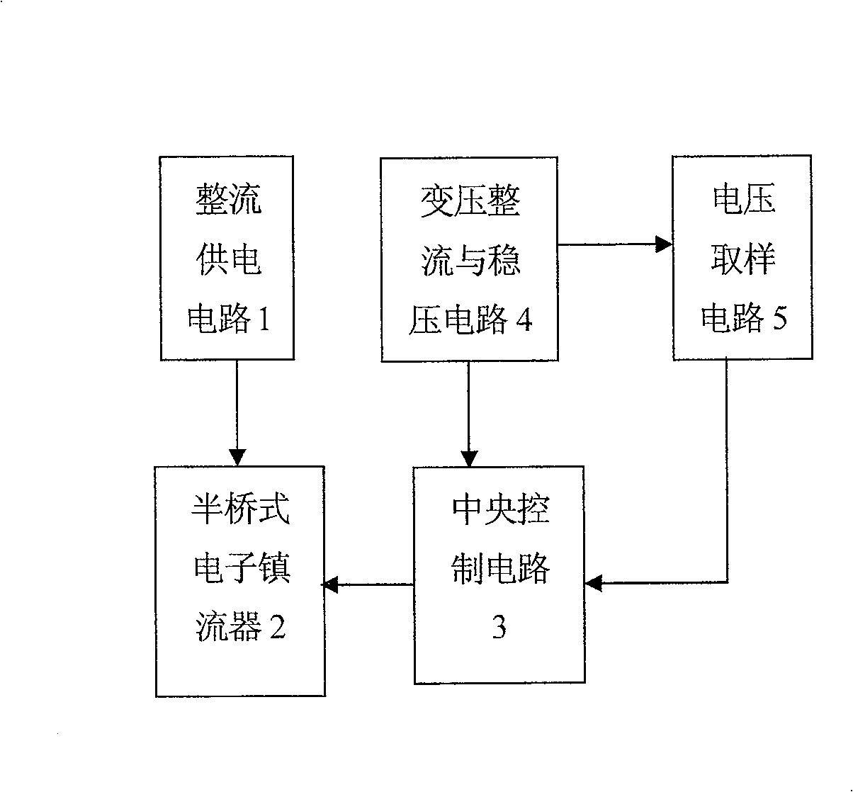
[0021] See figure 1 , The electronic ballast used in fluorescent lamps has a rectification power supply circuit 1, a half-bridge electronic ballast 2, a central control circuit 3, a transformer rectification and voltage stabilization circuit 4 and a voltage sampling circuit 5.

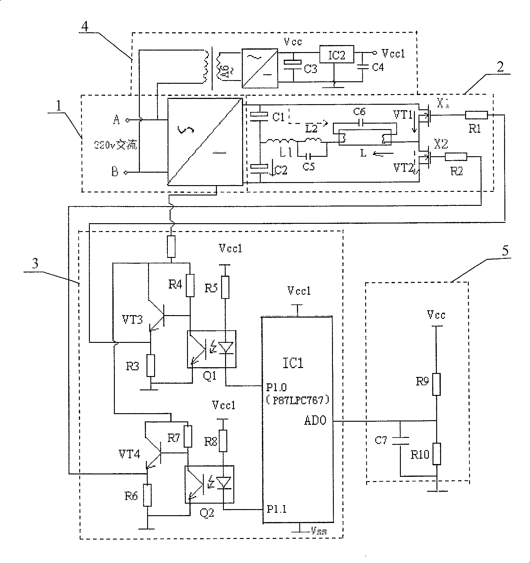
[0022] See figure 2 , In the rectification power supply circuit 1, the AC input terminals A and B of the ballast are connected to the 220V city AC.

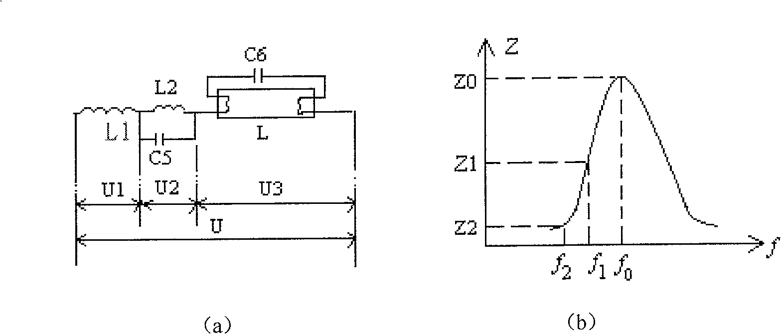
[0023] The series resonant circuit of the half-bridge electronic ballast 2 includes two VMOS field effect transistors VT1 and VT2, a starting circuit composed of a choke coil L1 and a filament preheating path capacitor C6, and a transformer composed of an inductance L2 and a capacitor C5 connected in parallel. Resistance circuit, filter capacitors C1 and C2.

[0024] Central control circuit 3 comprises central controller (model is the single-chip microcomputer IC1 of P87LPC767) and the driving circuit that links to each other with the control output en...

Embodiment 2

[0034] On the basis of Embodiment 1, this embodiment is modified as follows. The electronic ballast and its working method of this embodiment can be applied to HID lamps.

[0035] The working method of electronic ballasts applied to HID lamps, including:

[0036] ①. The P1.0 terminal and P1.1 terminal of the single-chip microcomputer IC1 output high and low levels alternately, and the two VMOS field effect transistors VT1 and VT2 in the half-bridge electronic ballast 2 are controlled by the driving circuit to be turned on and off alternately, Make the starting circuit generate series resonance and generate inverter frequency until the fluorescent tube or HID lamp is triggered to light up. ②, the resonant frequency of the rheostat circuit is always lower than the inverter frequency generated by the half-bridge electronic ballast 2; the central control circuit 3 detects the voltage fluctuation of the municipal AC through the voltage sampling circuit 5; when the measured municipa...


PUM


Abstract

The invention relates to an electronic ballast and its working method. It has a half-bridge electronic ballast for driving fluorescent lamps or HID lamps to emit light; It also has: a central control circuit connected to the inverter frequency control terminal of the half-bridge electronic ballast; a voltage sampling circuit connected to the voltage detection signal input terminal of the central control circuit; transformer rectification and stabilization The voltage circuit is connected with the city AC and is used to provide power to the central control circuit and the voltage sampling circuit; the voltage sampling circuit is used to detect the voltage fluctuation of the city AC through the transformer rectification and voltage stabilization circuit; Fluctuation controls the inverter frequency of the half-bridge electronic ballast to keep the luminance of fluorescent lamps or HID lamps constant. The electronic ballast of the invention can improve the light efficiency of the fluorescent lamp or the HID lamp, prevent flickering and keep the brightness constant.

Description

technical field [0001] The invention relates to an electronic ballast used in fluorescent lamps and high-intensity gas discharge lamps and its working method. Background technique [0002] Fluorescent lamps and high-intensity discharge lamps (HID lamps) are new energy-saving electric light sources, and the ballasts used with them are often inductive ballasts. Inductive ballasts have large consumables, and the reactive power loss is large when they work at a frequency of 50-60 Hz; at the same time, the fluorescent lamps or HID lamps have low lighting efficiency, are prone to flicker, and the brightness changes with the change of the grid voltage, which affects the service life of the lamps. It is not conducive to eye protection when used in office lighting. [0003] Chinese patent document CN2579135Y discloses a high-power electronic ballast, which is composed of a filter, a rectification filter circuit, an oscillation circuit, a switch amplifier circuit, a short circuit pro...

Claims


Application Information

Patent Timeline
Patent Type & Authority Patents(China)
IPC IPC(8): H05B41/14
Inventor 杨龙兴
Owner 江苏威科变压器有限公司
Why Eureka
Try Eureka