Light emitting diode driving circuit

A technology of light-emitting diodes and driving circuits, which is applied in the directions of circuits, electroluminescent light sources, and electric lamp circuit layout, etc., can solve problems such as the reduction of the brightness of LED14

Inactive Publication Date: 2009-07-01
MITSUMI ELECTRIC CO LTD
View PDF1 Cites 0 Cited by
  • Summary
  • Abstract
  • Description
  • Claims
  • Application Information

AI Technical Summary

Problems solved by technology

[0013] In the existing light-emitting diode drive circuit, because even if the ambient temperature rises, the current I flowing through the LED14 L is also constant, so when the ambient temperature rises, the forward voltage drop V of LED14 F When lowering, there is a problem that the brightness of LED14 is lowered

Method used


Image

  • Light emitting diode driving circuit
  • Light emitting diode driving circuit
  • Light emitting diode driving circuit

Examples


Embodiment Construction

[0039] Embodiments of the present invention will be described below with reference to the drawings.

[0040]

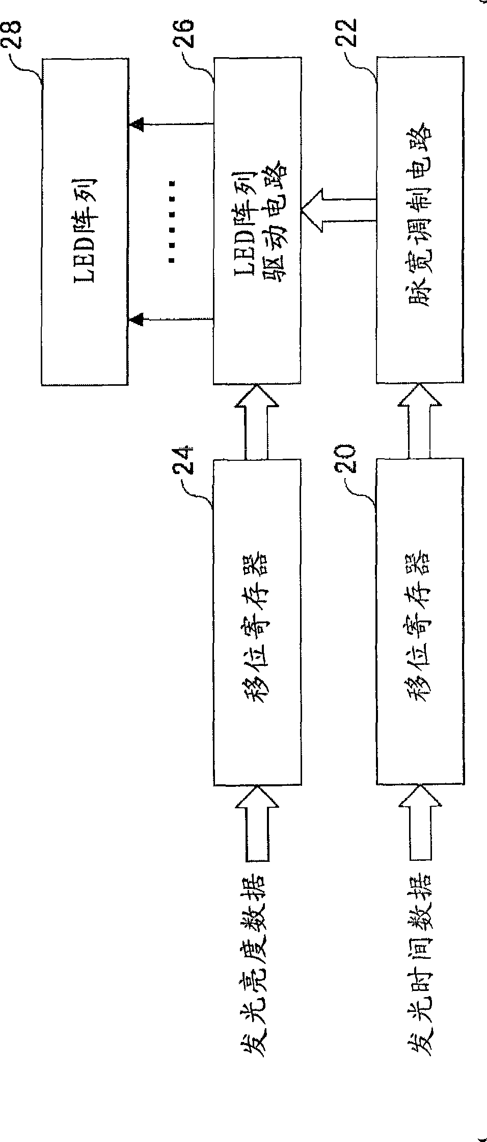
[0041] figure 2 A block diagram showing an embodiment of an LED array device using the light emitting diode driving circuit of the present invention. The LED array device is, for example, a 48-channel structure.

[0042] In this figure, in the shift register 20, 6-bit luminous time data is supplied in time series with, for example, 48 channels for one channel, and after the data is sequentially shifted and latched in the shift register 20, it is It is supplied to the pulse width modulation circuit 22 . The pulse width modulation circuit 22 generates light emission pulses having a pulse width indicated by light emission time data for each channel, and supplies light emission pulses for 48 channels to the LED array drive circuit 26 .

[0043] In the shift register 24, 6-bit luminescence time data is supplied to one channel, for example, in time series of 48 channe...


PUM


Abstract

A light emitting diode driving circuit is provided with a reference current section for generating a reference current, and a current outputting section for generating a driving current based on the reference current by using a current mirror circuit, and supplying the light emitting diode with the driving current. The reference current section is provided with a temperature characteristic element having negative temperature characteristics.

Description

technical field [0001] The present invention relates to a light-emitting diode drive circuit, and relates to a light-emitting diode drive circuit for driving each of a plurality of light-emitting diodes arranged. Background technique [0002] As a member for exposing a photoreceptor to light in a printer or the like, an LED array in which light emitting diodes (hereinafter referred to as "LEDs") are arranged in a line is used. As a drive circuit for driving each LED of such an LED array, there are drive circuits described in Patent Documents 1, 2, and the like, for example. [0003] figure 1 A circuit configuration diagram showing an example of a conventional light emitting diode drive circuit. The drive circuit is integrated into a semiconductor circuit. [0004] In this figure, a reference voltage Vref is applied to the inverting input terminal of the operational amplifier 10 by a reference voltage source. The output terminal of the operational amplifier 10 is connecte...

Claims


Application Information

Patent Timeline
Patent Type & Authority Applications(China)
IPC IPC(8): H01L33/00H05B37/02
CPCH05B33/0848H05B45/14
Inventor 山口公一铃木大介
Owner MITSUMI ELECTRIC CO LTD
Why Eureka
Try Eureka