LED dimming circuit, led module, and dimming method of led module

A technology of LED modules and dimming circuits, applied in electroluminescent light sources, light sources, electric light sources, etc., can solve the problems of large control circuit area, large LED module volume, large PCB board area, etc., and reduce production costs. , The effect of simple color temperature adjustment and constant color temperature

Active Publication Date: 2019-01-29
RAYBEN TECH ZHUHAI
View PDF10 Cites 0 Cited by
  • Summary
  • Abstract
  • Description
  • Claims
  • Application Information

AI Technical Summary

Problems solved by technology

[0005] However, in this solution, the warm white LED chipset and the cool white LED chipset are adjustable separately, so the circuit structure is complicated, especially a knob potentiometer needs to be set as a switch to control the on-off of the two groups of LED chipsets. , leading to a large volume of the LED module, and a large area of ​​the control circuit, resulting in a large area of ​​the PCB board, thereby increasing the production cost of the LED module
In addition, when adjusting the color temperature of the LED module, manual adjustment is required, which also brings inconvenience to the color temperature adjustment of the LED module

Method used


Image

  • LED dimming circuit, led module, and dimming method of led module
  • LED dimming circuit, led module, and dimming method of led module
  • LED dimming circuit, led module, and dimming method of led module

Examples


Embodiment Construction

[0034] The LED module of the present invention can be used in lighting systems, such as lighting fixtures for lighting, and can also be applied to lighting fixtures for special purposes, such as lighting fixtures for plant generation, decoration, and animal attraction. Preferably, the lighting system using the LED module has a housing, and the LED module is arranged in the housing. Moreover, the LED module of the present invention is an LED module with adjustable color temperature, that is, the light emitted by the LED module has two extreme color temperatures, and can gradually change from the color temperature of the first extreme position to the color temperature of the second extreme position. .

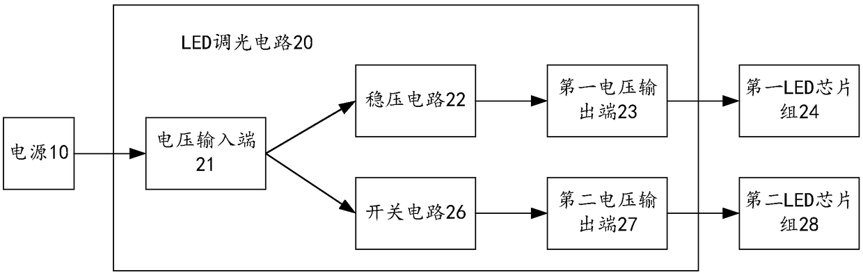
[0035] see figure 1 , the LED module of this embodiment includes a power supply 10, an LED dimming circuit 20, a first LED chipset 24, and a second LED chipset 28, wherein the power supply 10 may be a power supply including a battery, and is provided with a dimmer, It is used t...


PUM


Abstract

The invention relates to an LED dimming circuit, an LED module, and a dimming method for an LED module. The circuit includes a voltage input terminal, a first voltage output terminal, and a second voltage output terminal, wherein the voltage input terminal and the first voltage output terminal A voltage stabilizing circuit is connected between the terminals, and a switch circuit is connected between the voltage input terminal and the second voltage output terminal, and the switch circuit is switched on and off according to the voltage value input by the voltage input terminal. The LED module includes the above-mentioned LED dimming circuit and two sets of LED chips. The method includes providing a voltage to the voltage input terminal, and the output voltage of the voltage input terminal provides a stable voltage to the first LED chipset after passing through the voltage stabilizing circuit, and the first LED chipset emits light; the voltage input at the voltage input terminal is higher than that of the switch circuit When the threshold voltage is turned on, the switch circuit is turned on and provides voltage to the second LED chipset, and the second LED chipset emits light. The invention can conveniently realize the adjustment of the color temperature of the LED module.

Description

technical field [0001] The invention relates to the field of semiconductor light-emitting devices, in particular to an LED dimming circuit and an LED module with the dimming circuit, and also relates to a dimming method for the LED module. Background technique [0002] LED lighting devices use light-emitting diodes (LEDs) as light-emitting elements, which have the advantages of energy saving, environmental protection, low power consumption, and long service life, and are widely used in various lighting occasions. An existing LED lighting device adopts two sets of LED chipsets, one of which is a cold light LED chipset, which can emit cool-toned light after being powered on, and the other set of LED chipsets is a warm light chipset, which can Afterwards, it can emit warm-toned light. In this way, people can control the luminance of the two sets of LED chips by controlling the voltage applied to the two sets of LED chips, thereby changing the overall color temperature of the L...

Claims


Application Information

Patent Timeline
Patent Type & Authority Patents(China)
IPC IPC(8): H05B33/08H05B44/00
CPCH05B45/10H05B45/37Y02B20/30
Inventor 杜小军赵洁萍严国安胡启钊聂沛珈
Owner RAYBEN TECH ZHUHAI
Why Eureka
Try Eureka