Eureka AIR delivers breakthrough ideas for toughest innovation challenges, trusted by R&D personnel around the world.

A Constant Current Source Driving Circuit Based on Double-loop Negative Feedback

A driving circuit and constant current source technology, applied in the direction of adjusting electrical variables, instruments, control/regulating systems, etc., can solve the problems of small driving current, increasing chip area, raising the VD2 voltage of the drain terminal of PO2 transistors, etc., to achieve reliability. High, simple structure

Active Publication Date: 2021-02-02
西安中颖电子有限公司
View PDF6 Cites 0 Cited by
  • Summary
  • Abstract
  • Description
  • Claims
  • Application Information

AI Technical Summary

Problems solved by technology

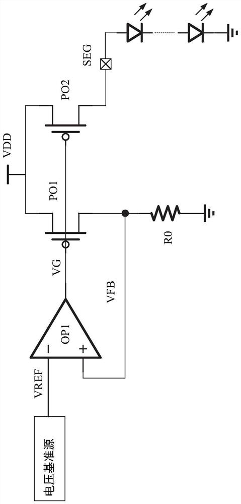
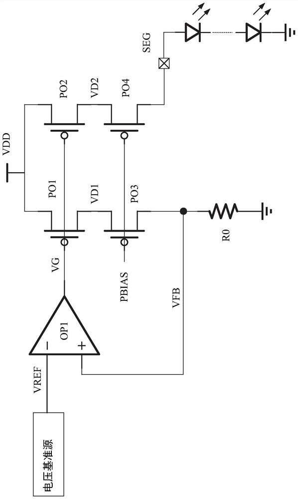
But this structure needs to pay a large area price: first, because the output current to the SEG port is very large, the area of ​​the PO4 transistor itself needs to be large; second, the PO4 transistor in series will further increase the leakage of the PO2 transistor. The voltage of the terminal VD2 further reduces the source-drain voltage of the PO2 transistor |VDS|
According to the linear area current formula of the PMOS transistor, the driving current is relatively small, and the driving ability can only be increased by increasing the width of PO2, which increases the chip area.

Method used


Image

  • A Constant Current Source Driving Circuit Based on Double-loop Negative Feedback
  • A Constant Current Source Driving Circuit Based on Double-loop Negative Feedback
  • A Constant Current Source Driving Circuit Based on Double-loop Negative Feedback

Examples


Embodiment Construction

[0033] The detailed features and advantages of the present invention are described in detail below in the specific embodiments, the content of which is sufficient to enable any person skilled in the art to understand the technical content of the present invention and implement it accordingly, and according to the specification, claims and drawings disclosed in this specification , those skilled in the art can easily understand the related objects and advantages of the present invention.

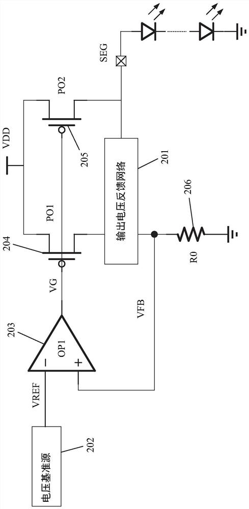
[0034]The invention adds an output voltage feedback network circuit on the basis of the traditional constant current source circuit to realize high-precision LED constant current output that is not affected by the external environment, thereby forming a double-loop negative feedback structure LED constant current source drive circuit. The output voltage feedback network circuit can be realized by a high-gain amplifier or a simple current mirror structure, so it has the advantages of simple str...


PUM


Abstract

The present invention provides a constant current source drive circuit based on double-loop negative feedback. The constant current source drive circuit includes: a voltage reference source, a first high-gain amplifier, a resistor, a first transistor, a second transistor, and an output voltage feedback network circuit. The output voltage feedback network circuit can monitor the change of the SEG port voltage in real time, and control the gate terminal voltage of the first transistor and the second transistor through the output voltage feedback network circuit, the resistor and the first high-gain amplifier to keep the output current constant , thereby solving the problems existing in the traditional LED constant current source driving circuit.

Description

technical field [0001] The invention relates to a driving circuit, in particular to an LED constant current source driving circuit. Background technique [0002] The LED constant current source drive circuit has the advantages of precisely controlling the LED luminance and improving the service life of the LED, and has been widely used. [0003] The traditional LED constant current source drive circuit generally adopts such as Figure 1A In the architecture shown, the working principle of the circuit is as follows: the voltage reference source generates a constant voltage reference VREF that does not change with the external environment, the high-gain amplifier OP1 works in a closed-loop negative feedback state, and its non-inverting input and inverting input have virtual short characteristics , so that the voltage VFB of its non-inverting input terminal is also the reference voltage VREF, and this voltage is added to both ends of the resistor R0, so the current flowing thro...

Claims


Application Information

Patent Timeline
Patent Type & Authority Patents(China)
IPC IPC(8): G05F1/56
Inventor 白胜天吉博
Owner 西安中颖电子有限公司
Why Eureka
Eureka Blog
Learn More