
LED drive circuit with high power factor and no flicker
A technology of LED driving and high power factor, which is applied in the direction of electric lamp circuit layout, electric light source, lighting device, etc., can solve unrealistic problems, increase output capacitor capacity, etc., and achieve the effect of solving stroboscopic and improving power factor
- Summary
- Abstract
- Description
- Claims
- Application Information
AI Technical Summary
Problems solved by technology
Method used
Image

Examples
Embodiment approach
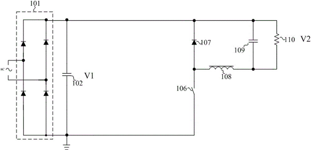
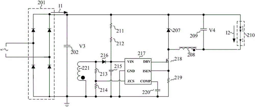
[0030] The inventive idea of the present invention is: as figure 1 The topology of the classic step-down power factor correction circuit shown in the actual work not only needs to add a dedicated power factor correction constant current driver chip, but also produces stroboscopic phenomenon. In order to overcome the above defects, we need to improve the traditional buck structure. Based on the above purpose, the present invention improves the traditional step-down structure to form a new circuit structure. In this new circuit structure, it only needs to add the existing general-purpose power management control chip to improve the power factor at the same time. And to avoid the purpose of stroboscopic phenomenon.
[0031] Figure 4 It is a structural schematic diagram of the first embodiment of the present invention, Figure 4 Including: rectifier bridge 401, capacitor 402, inductor 403, diode 404, capacitor 405, switch tube 406, diode 407, inductor 408, capacitor 409 and ...
PUM
 Abstract
Description
Claims
Application Information