
Control circuit and control method of flyback convertor and alternating current-direct current power converting circuit applying control circuit of flyback convertor

A flyback converter and control circuit technology, applied in the field of power supply, can solve the problems of increasing circuit cost and size, unfavorable chip miniaturization, package design, and complicated control scheme, so as to save chip size and improve pin utilization , The effect of saving chip pins

Active Publication Date: 2012-08-15
SILERGY SEMICON TECH (HANGZHOU) CO LTD
View PDF7 Cites 58 Cited by
  • Summary
  • Abstract
  • Description
  • Claims
  • Application Information

AI Technical Summary

Problems solved by technology

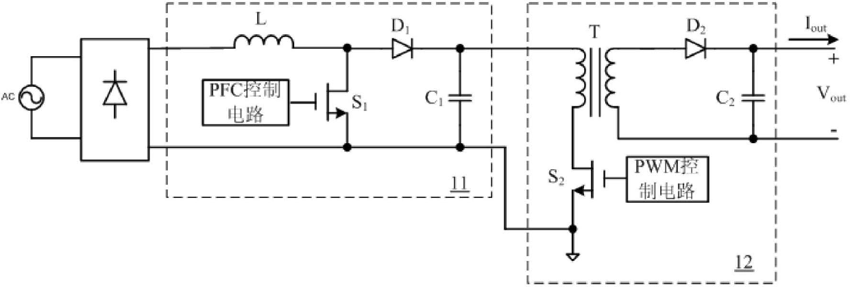
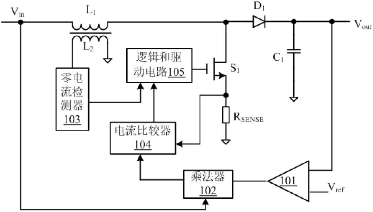
[0007] It can be seen that the power factor correction implementation scheme of the prior art needs to adopt a two-stage power conversion circuit, which obviously increases the cost and size of the circuit; in addition, the implementation scheme of the power factor correction of the prior art needs to sample the input voltage, and through analog multiplication The device receives the input voltage to obtain a sine half-wave signal that the inductor current must follow compulsively. Such an implementation scheme is complicated; and for integrated circuits, a separate pin is bound to be required to receive the input voltage, which is not conducive to the chip The miniaturization and package design of the

Method used


Image

  • Control circuit and control method of flyback convertor and alternating current-direct current power converting circuit applying control circuit of flyback convertor
  • Control circuit and control method of flyback convertor and alternating current-direct current power converting circuit applying control circuit of flyback convertor
  • Control circuit and control method of flyback convertor and alternating current-direct current power converting circuit applying control circuit of flyback convertor

Examples


Embodiment Construction

[0047] Several preferred embodiments of the present invention will be described in detail below with reference to the accompanying drawings, but the present invention is not limited to these embodiments. The present invention covers any alternatives, modifications, equivalent methods and schemes made on the spirit and scope of the present invention. In order to provide the public with a thorough understanding of the present invention, specific details are set forth in the following preferred embodiments of the present invention, but those skilled in the art can fully understand the present invention without the description of these details.

[0048] refer to figure 2 , shows a functional block diagram of a control circuit of a flyback converter according to an embodiment of the present invention. In this embodiment, the control circuit 200 of the flyback converter includes a turn-on signal generation circuit 21 , a turn-off signal generation circuit 22 and a control signal g...


PUM


Abstract

The invention relates to a control circuit and a control method of a flyback convertor and an alternating current-direct current power converting circuit applying the control circuit of the flyback convertor. Within each switch period, an opening signal generating circuit is used for receiving drain-source voltage of a power switch in the flyback converter; when the drain-source voltage reaches valley value, opening signal is generated to control the turn-on of the power switch; a turn-off signal generating circuit is used for generating a turn-off signal after the power switch turns on and a turn-on time interval is completed according to a feedback error signal of a received output electric signal for representing the flyback converter; and the turn-off signal controls the power switch to turn off, so as to lead input current and input voltage of the flyback converter in a same phase and keep the output electric signal of the flyback converter constant.

Description

technical field [0001] The present invention relates to the field of power supplies, more specifically, to a control circuit and control method of a flyback converter and an AC-DC power conversion circuit using the same. Background technique [0002] Active power factor correction (active power factor correction, APFC) is an important way to use electric energy efficiently and with low pollution. It adds a power conversion circuit between the bridge rectifier and the output capacitor filter to make the power factor close to 1. The active power factor correction circuit works in a high-frequency switching state, has the characteristics of small size, light weight, high efficiency, etc., and has become a new hot spot in the research of power electronics technology. [0003] In the prior art, power factor correction technology is widely used in off-line switching power supplies. Most of the existing switching power supplies with power factor correction function include a two-s...

Claims


Application Information

Patent Timeline
Patent Type & Authority Applications(China)
IPC IPC(8): H02M3/335H02M7/04
CPCH02M1/4258H02M3/33523Y02B70/10
Inventor 陈伟
Owner SILERGY SEMICON TECH (HANGZHOU) CO LTD
Learn More