Circuit for dimming or speed regulation control and control method

A control circuit and speed regulation technology, which is applied in the fields of excitation or armature current control, energy-saving control technology, lamp circuit layout, etc., can solve problems such as large ineffective electric power loss, and achieve normal blocking, large adjustment range, and good linearity Effect

Inactive Publication Date: 2010-10-20
HANGZHOU SOMA ELECTRONICS
View PDF3 Cites 56 Cited by
  • Summary
  • Abstract
  • Description
  • Claims
  • Application Information

AI Technical Summary

Problems solved by technology

Its disadvantages are: First, the dynamic dumb load changes its current input in response to the operation of the converter circuit. The so-called "operation of the converter circuit" is the operation of the circuit on the LED drive (output), that is to say, "dynamic dumb load" In response to the size of the LED drive output of the "converter circuit", the dynamic value of the dummy load decreases when the LED drive output is large, and vice versa. Since the entire converter circuit is a capacitive structure, the change in the drive output of the converter circuit The value at the time point is not necessarily consistent with the load value of the thyristor at this time point, because the output of the LED converter circuit decreases, which is generally a low valley value immediately after the circuit has a high output peak value (PWM switch Mode output characteristics), the appearance of the low valley value, dynamic dumb load response, and load value compensation, but, due to the capacitive characteristics of the circuit, there is a capacitor charging and discharging time difference when the change is reflected to the thyristor dimmer, which will The dynamic dumb load responds at an inaccurate (leading) time; the second is that only relying on a dynamic dumb load to respond to the operation of the converter circuit to change its current introduction to the method of providing load to the dimmer will have greater inefficiency electrical power loss

Method used


Image

  • Circuit for dimming or speed regulation control and control method
  • Circuit for dimming or speed regulation control and control method
  • Circuit for dimming or speed regulation control and control method

Examples


Embodiment 1

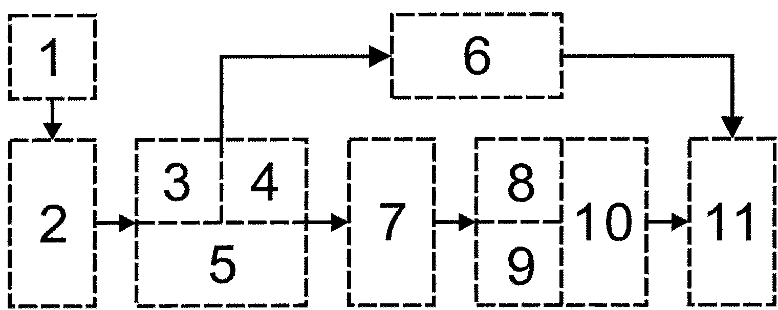
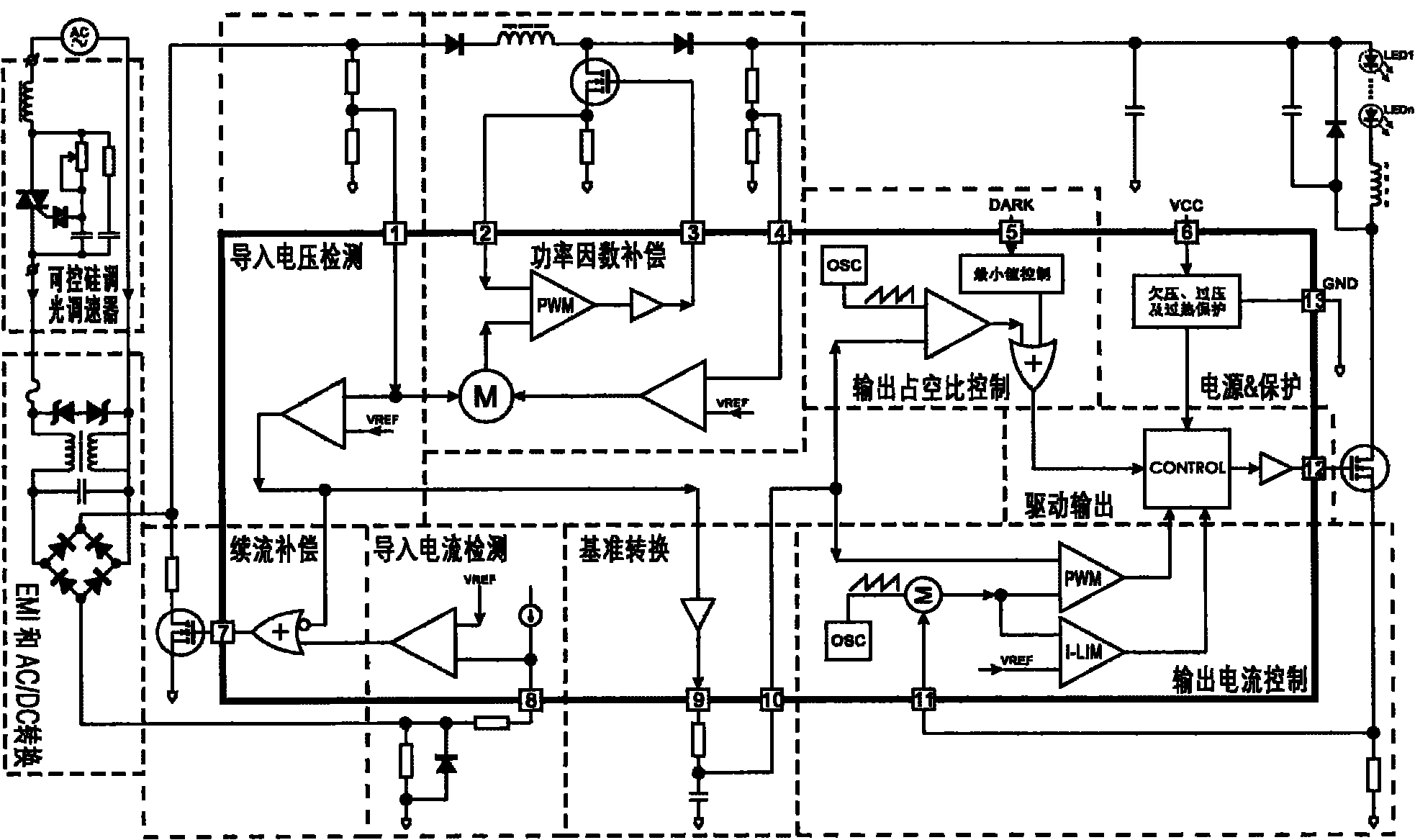
[0028] Example 1: refer to the attached figure 1 and 2 . The detection compensation circuit used for the dimming or speed control circuit is composed of a voltage detection circuit 3, a current detection circuit 4, a freewheeling compensation circuit 5, and a power factor compensation circuit 6. The voltage detection circuit 3 is converted through EMI and AC / DC. The power supply terminal of circuit 2 detects the change of the output voltage of the thyristor dimming or the AC phase-cutting operation of the governor 1, and generates the trigger current control signal and the dimming or speed regulation control signal. The current detection circuit 4 passes EMI and AC / DC The power supply terminal of the conversion circuit 2 detects the change of the current output by the thyristor dimming or the AC phase-cutting operation of the governor 1, and generates a dynamic compensation control signal for the thyristor dimming or the maintaining current of the governor. The freewheeling c...

Embodiment 2

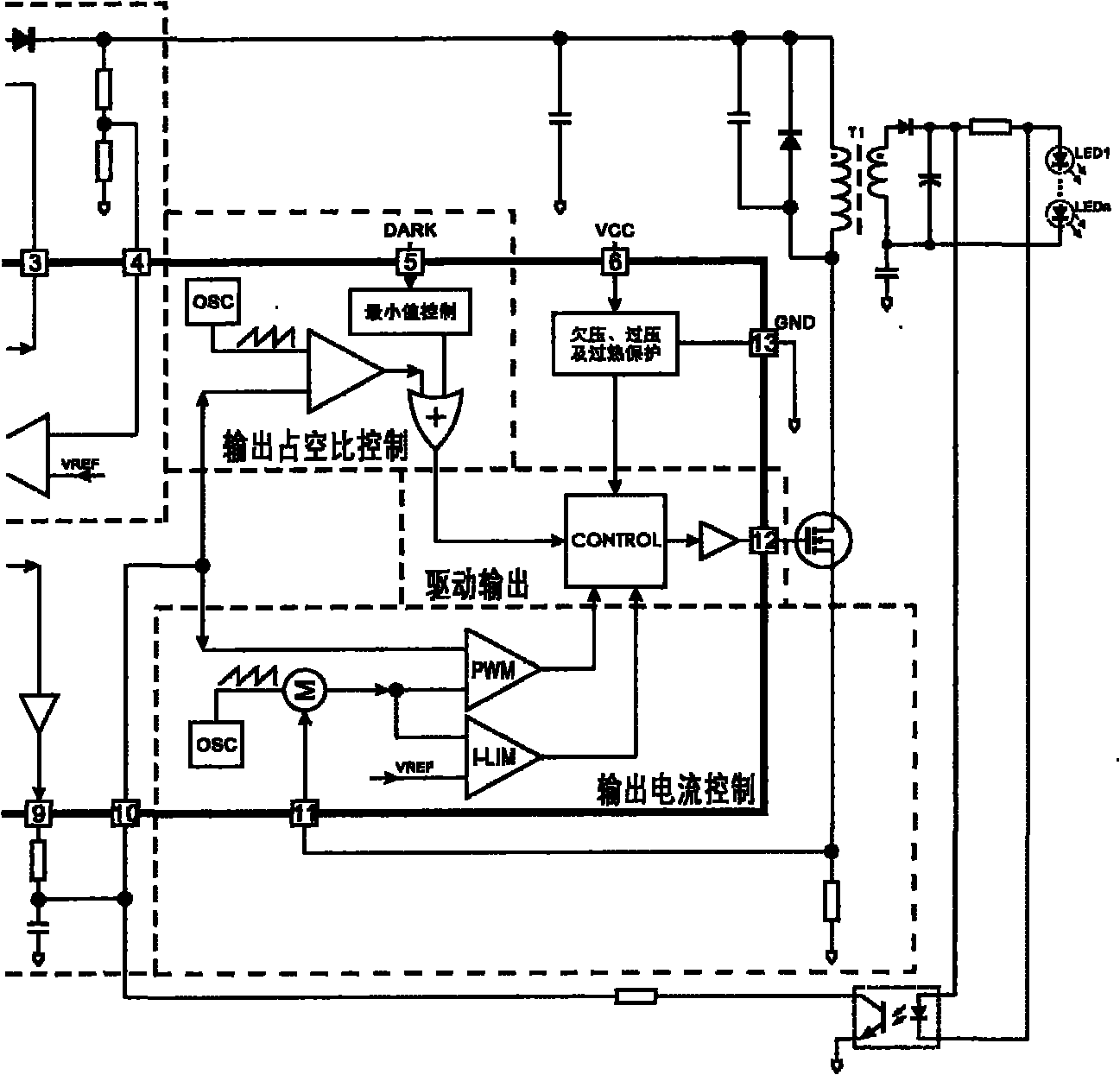
[0044] Example 2: On the basis of Example 1, refer to the attached image 3 . The detection and compensation method used for dimming or speed regulation control circuit adopts the detection method combining the change of the output voltage and the change of the current magnitude of the thyristor dimming or the AC phase-cut operation of the governor 1 to detect the thyristor dimming or The operating state of the governor 1 being blocked and conducting; the compensation method combining power factor compensation and freewheeling compensation is used to provide the trigger current and maintenance current of the thyristor dimming or governor to ensure the thyristor dimming. Or the normal blocking and conduction of the governor, and reduce the electric power loss caused by the freewheeling compensation and improve the efficiency of the circuit system.

[0045] The method for detecting the change of the output voltage of the thyristor dimming or the AC phase-cutting operation of th...

Embodiment 3

[0049] Example 3: refer to the attached Figures 1 to 3 . A dimming or speed-adjusting control circuit composed of a detection and compensation circuit, which includes a thyristor dimming or speed-adjusting control circuit, and the voltage detection circuit 3 in the thyristor dimming or speed-adjusting control circuit generates and the thyristor. The AC phase-cutting operation of the dimming or speed governor 1 outputs a pulse signal whose size changes synchronously, the pulse signal is converted into a level signal by the reference conversion circuit 7, and the level signal is passed through the output duty cycle control circuit 8 and the output current control circuit. 9 acts on the drive control circuit 10 at the same time to realize the composite control of the load output duty cycle and the load working current; the current detection circuit 4 in the thyristor dimming or speed regulation control circuit detects the thyristor dimming or speed regulation The magnitude of t...


PUM


Abstract

The invention relates to the field of dimming and speed regulation related to illumination, motors and electronics, in particular to a motor-driven circuit for dimming or speed regulation control which is suitable for illumination of a silicon-controlled dimmer or adjustment of a silicon-controlled speed regulator and a control method. A detection compensation circuit for maintaining the normal work of the silicon-controlled dimmer consists of a voltage detection circuit, a current detection circuit, a follow current compensation circuit and a power factor compensation circuit; the on-off running state of the silicon-controlled dimmer or speed regulator is detected by a detection method combining output voltage change and current change of the silicon-controlled dimmer or speed regulator;the on-off and trigger running conditions of the silicon-controlled dimmer are provided by adopting a compensation method combining power factor compensation and follow current compensation; a control circuit of a load consists of a datum transformation circuit, an output duty cycle control circuit, an output current control circuit and a drive output circuit and produces a control signal by detecting mains supply AC phase-shedding operation output of the silicon-controlled dimmer or speed regulator; and the output power of the load is controlled by a load output duty cycle and load working current compound control method so as to realize large output power adjustable range of the load and high linearity of the adjusting process.

Description

technical field [0001] The invention relates to the field of dimming and speed regulation related to lighting, motor and electronics, in particular, to a dimming or speed regulating device suitable for thyristor dimming lighting or speed regulator to regulate motor drive. A control circuit and a control method belong to the field of lighting and motor drive control circuit manufacturing. Background technique [0002] CN1843061A, titled "Dimming Circuit for LED Lighting Equipment and Means for Keeping TRIAC On", which includes providing a dynamic dummy load in case the LED electronics do not provide sufficient load due to start-up problems or ringing in the circuit While providing a load to the dimmer, the dynamic dummy load provides reduced current when the LED and its converter electronics provide sufficient current draw from the dimmer. The system typically includes a power supply electrically connected to a phase-controlled dimmer electrically connected to a converter ci...

Claims


Application Information

Patent Timeline
Patent Type & Authority Applications(China)
IPC IPC(8): H05B37/02H02P7/28
CPCY02B20/42Y02B20/40
Inventor 潘忠浩
Owner HANGZHOU SOMA ELECTRONICS
Why Eureka
Try Eureka