Cold cathode fluorescence tube device

A fluorescent tube and cold cathode technology, which is applied to lighting devices, components of lighting devices, cooling/heating devices for lighting devices, etc. And other issues

Inactive Publication Date: 2006-01-18
SANKEN ELECTRIC CO LTD
View PDF3 Cites 1 Cited by
  • Summary
  • Abstract
  • Description
  • Claims
  • Application Information

AI Technical Summary

Problems solved by technology

However, the characteristic of the cold cathode fluorescent tube is that when the temperature of the glass tube wall exceeds a certain temperature, the brightness of the fluorescent tube will dr

Method used


Image

  • Cold cathode fluorescence tube device
  • Cold cathode fluorescence tube device
  • Cold cathode fluorescence tube device

Examples


Embodiment Construction

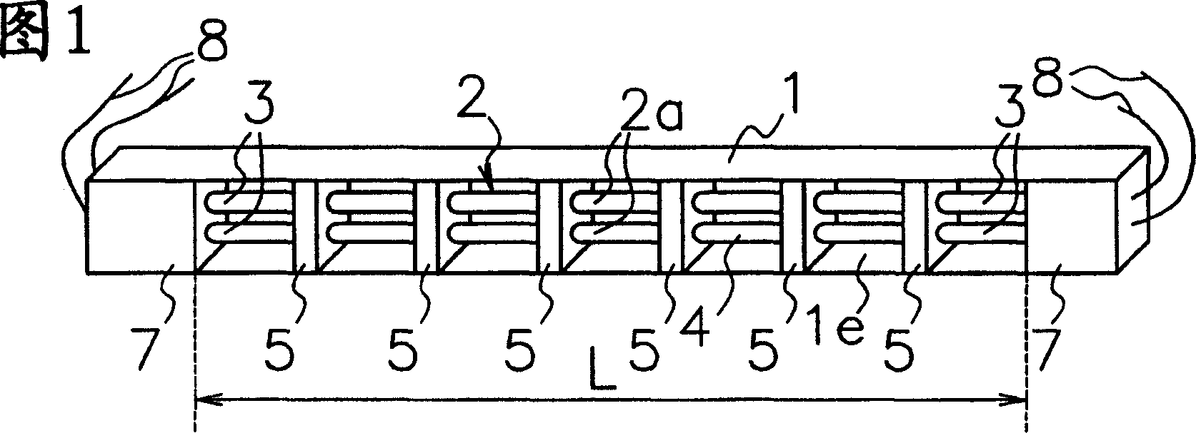
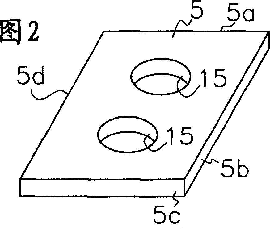
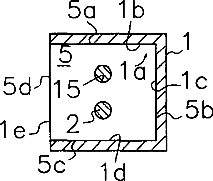
[0029] Below, refer to Figure 1- Figure 8 , an embodiment of the cold cathode fluorescent tube device according to the present invention applicable to the backlighting system will be described.

[0030] As shown in Figure 1, the cold cathode fluorescent tube device according to the present invention is provided with: a tube base 1, a junction box 7 located at both ends of the tube base 1, and a cold cathode fluorescent tube 2 with a glass tube 2a. Both end portions 3 of the cold cathode fluorescent tube 2 are supported by junction boxes 7 . The glass tube 2a is formed into a straight cylindrical shape with an inner diameter of 2 mm and a total length of 310 mm. The inside is filled with inert gas and mercury vapor to seal it. It is provided with (not shown): a pair of electrodes fixed at both ends of the glass tube 2a , the fluorescent film formed on the inner wall of the glass tube 2a, and a pair of terminals derived from both ends of the cold cathode fluorescent tube 2 tha...


PUM


Abstract

To restrain increase in tube temperature of an electric discharge tube when increasing tube current or the number of discharge tubes of a cold cathode fluorescence lamp apparatus.This cold cathode fluorescence lamp apparatus is provided with a holder 1 formed with a material of high heat radiation ability, a discharge tube 2 having both ends 3 supported by the holder 1, and a thermal-conductive bracket 5 fixed to a middle part 4 extending between the discharge tube 2 and both the end parts 3 and closely attached to the holder 1. Heat generated from the discharge tube 2 is discharged outside through the bracket 5 and the holder 1 thermally connected to the bracket 5 to prevent temperature increase of the discharge tube 2.

Description

technical field [0001] The present invention relates to a cold cathode fluorescent tube (lamp) device, in particular to a cold cathode fluorescent tube device capable of releasing heat generated by the cold cathode fluorescent tube to achieve high brightness and long life. Background technique [0002] For example, a backlight disclosed in Patent Document 1 below is well known. In this backlighting device, cold cathode fluorescent tubes are arranged at the side ends of the flat light guide body, and light introduced from the fluorescent tubes is emitted from the top of the light guide body by being reflected by a reflector formed under the light guide body. This device is equipped with a reflector that surrounds the fluorescent tube. The first gap formed between the fluorescent tube and the light guide side end is almost the same as the second gap formed between the fluorescent tube and the curved surface of the reflector. Moreover, the sum of the first gap and the second g...

Claims


Application Information

Patent Timeline
IPC IPC(8): G02F1/1335
CPCF21V19/00F21V19/0005F21V29/00H01J5/48H01J5/50H01J61/526H01J61/78
Inventor 山下丰美松原正昭
Owner SANKEN ELECTRIC CO LTD
Why Eureka
Try Eureka