

Electronic zeroing method for photoelectric rotary encoder
A shaft angle encoder and electronic technology, applied in the direction of instruments, conversion sensor output, measuring devices, etc., can solve the problems of complex circuit structure, troublesome manual operation, inconvenient zero adjustment, etc., and achieve simple circuit structure, less error-prone and accurate sex high effect
Inactive Publication Date: 2006-02-08
CHANGCHUN INST OF OPTICS FINE MECHANICS & PHYSICS CHINESE ACAD OF SCI
View PDF1 Cites 4 Cited by
- Summary
- Abstract
- Description
- Claims
- Application Information
AI Technical Summary
Problems solved by technology
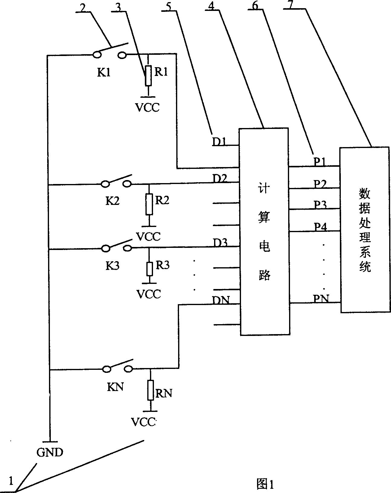
[0004] The structure of the circuit is complex, as many bits as there are encoders, there are as many dial switches and upper resistors as there are. Manual operation is cumbersome, time-consuming, easy to pull wrongly, and zero adjustment is inconvenient.
Method used
View moreImage
Smart ImageViewing Examples

Examples
Embodiment Construction
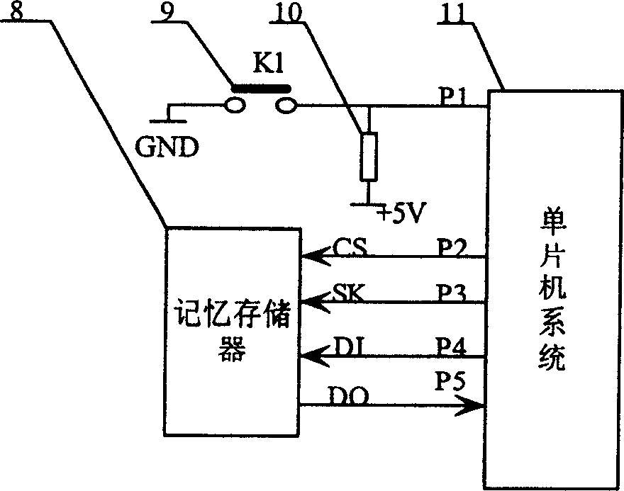
[0010] The method of the present invention designs the circuit according to the structure of the electronic zero adjustment circuit in the first step, and then controls the circuit according to the control program of the second step. The memory memory 8 uses 93C66 memory, the single-chip microcomputer is 8751, the resistance value of the pull-up resistor 10 is 1-10K, and the grounding power supply voltage is 5V.
Login to View More PUM
 Abstract
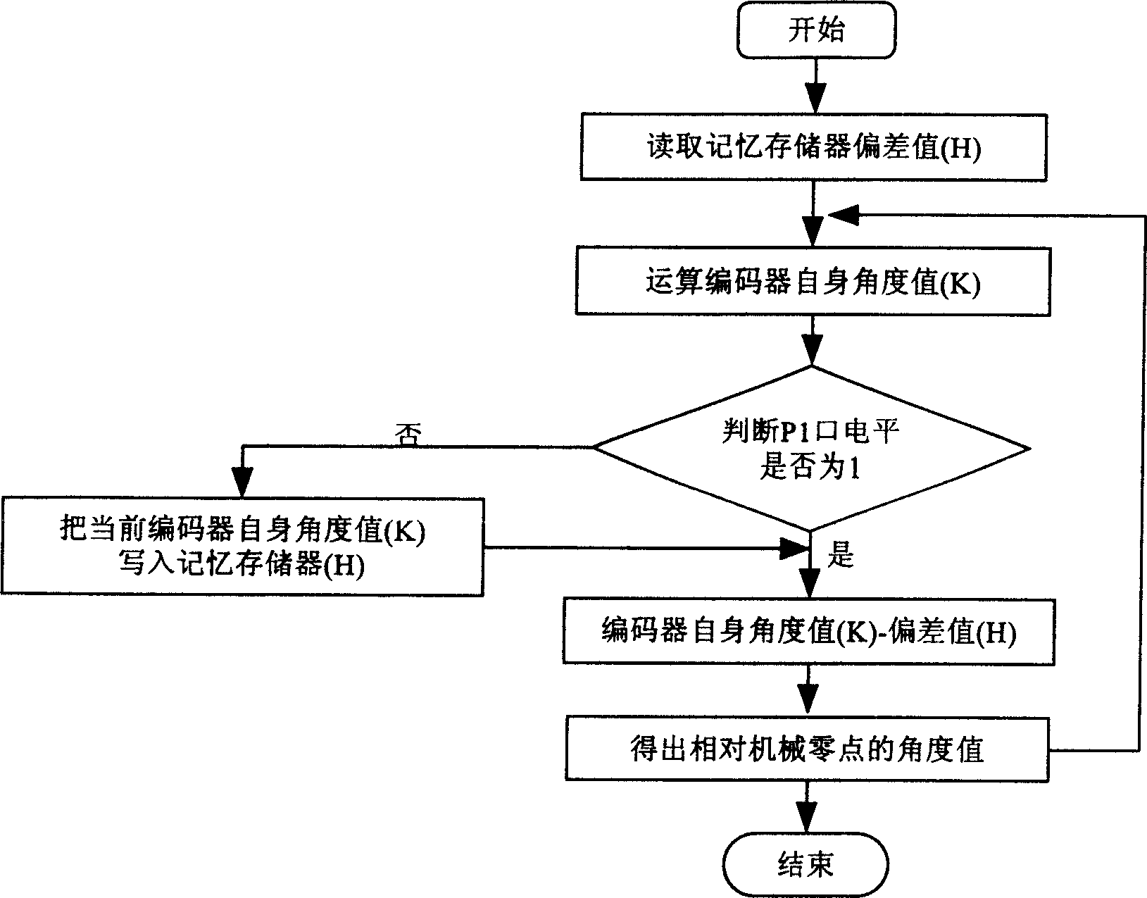
The invention relates to an electronic zero adjust method of optical-electricity shaft encoder in the field of optical-electricity measuring. First designing a electronic zero adjust circuit which comprises a memory storage device, a reset switch, a upper-pulling resistance and a signal chip computer, wherein the memory storage device possesses chip choosing end CS, clock interface SK, writing end DI and output end DO; one end of the reset switch is connected with the earth, the other end is connected with the P1 port; the upper-pulling resistance is positioned on the P1 port, the other end of the upper-pulling resistance is connected with the 5V power; the signal chip machine possesses input / output (I / O) interface P1 to P5, P1 is connected with the resistance end of the reset switch; P2 to P5 are separately connected with the chip choosing end CS, the clock interface SK, the writing end DI and the output end DO; second controlling the electronic zero adjust circuit by the preset electronic zero adjust program to achieve the clear impact.
Description
1. Technical Field [0001] The invention belongs to the technical field of photoelectric measurement and relates to an electronic zero adjustment method of a photoelectric shaft angle encoder. 2. Technical background [0002] The photoelectric shaft angle encoder is a representative photoelectric sensor device for photoelectric measurement of angular displacement. When the photoelectric shaft angle encoder is used for measurement, there are often the encoder zero position of the photoelectric shaft angle encoder and the rotation axis zero position of the measuring system. The non-coincidence has the phenomenon of angular deviation, which leads to the inaccurate angular displacement of the rotating shaft of the measurement system, which makes the measurement accuracy meaningless. Therefore, when the photoelectric shaft angle encoder is used to measure the angular displacement of the rotating shaft, the zero position of the code disc of the photoelectric shaft angle encoder must be ...
Claims
Login to View More Application Information
Patent Timeline
 Patent Type & AuthorityApplications(China)
IPC IPC(8): G01D3/00G01D18/00G01D5/347
Inventor张泽宇盖竹秋
OwnerCHANGCHUN INST OF OPTICS FINE MECHANICS & PHYSICS CHINESE ACAD OF SCI