Control system

A control system and controller technology, applied in the field of control systems, can solve problems such as a large number of steps, and achieve the effect of reducing installation costs and communication costs

Inactive Publication Date: 2006-12-20
YOKOGAWA ELECTRIC CORP
View PDF1 Cites 2 Cited by
  • Summary
  • Abstract
  • Description
  • Claims
  • Application Information

AI Technical Summary

Problems solved by technology

[0021] However, if, for example, a system constituent node is changed at a work site in a factory, it is necessary to correct the relevant DBs 11 to 15 of the system definition information group each time and generate a screen for displaying part, set the address of the system constituent node, and set the address of the system constituent node according to the correction The definition information download control function of the , therefore requires a large number of steps; this is a problem

Method used


Image

  • Control system
  • Control system
  • Control system

Examples


no. 1 example

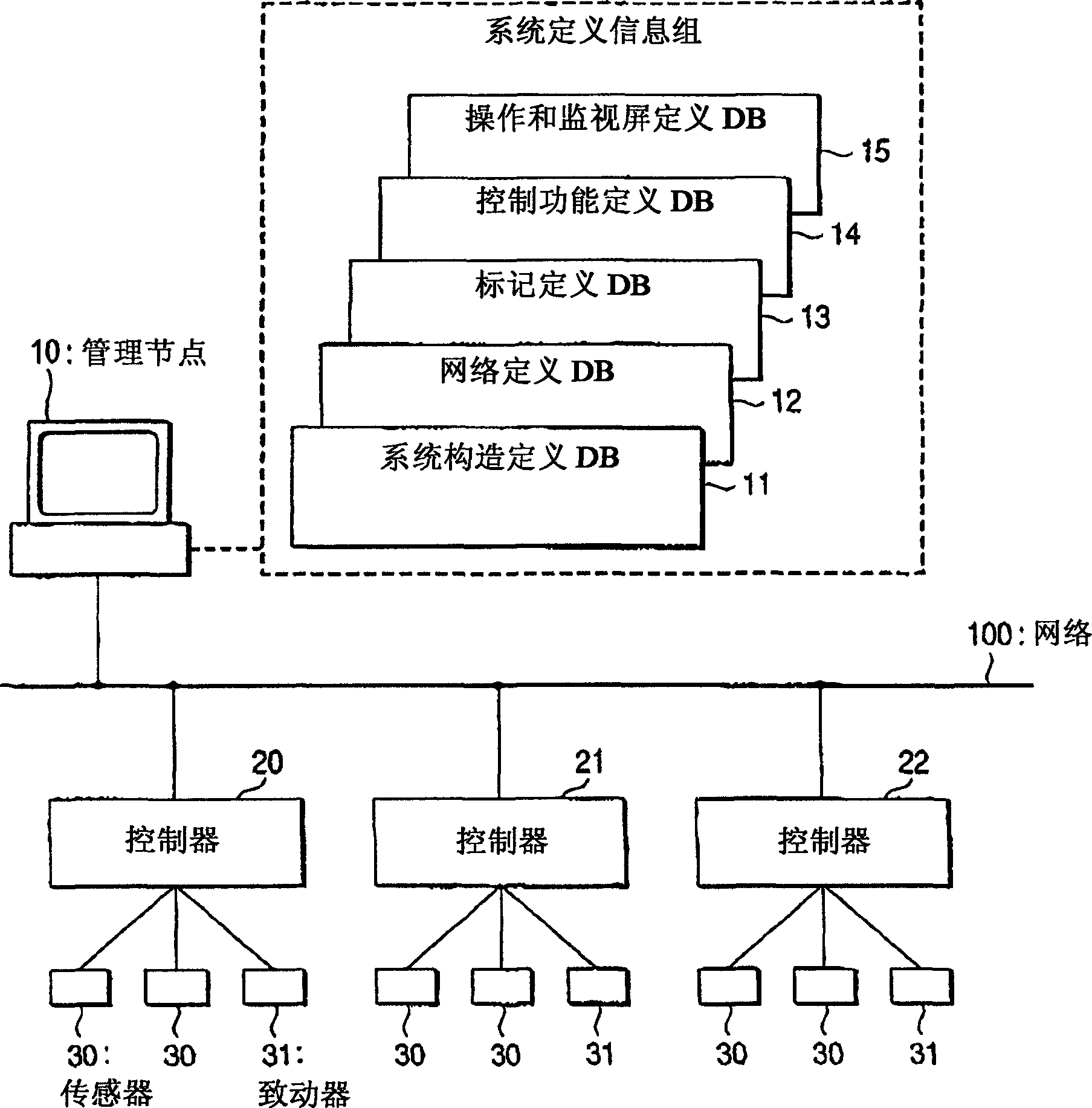
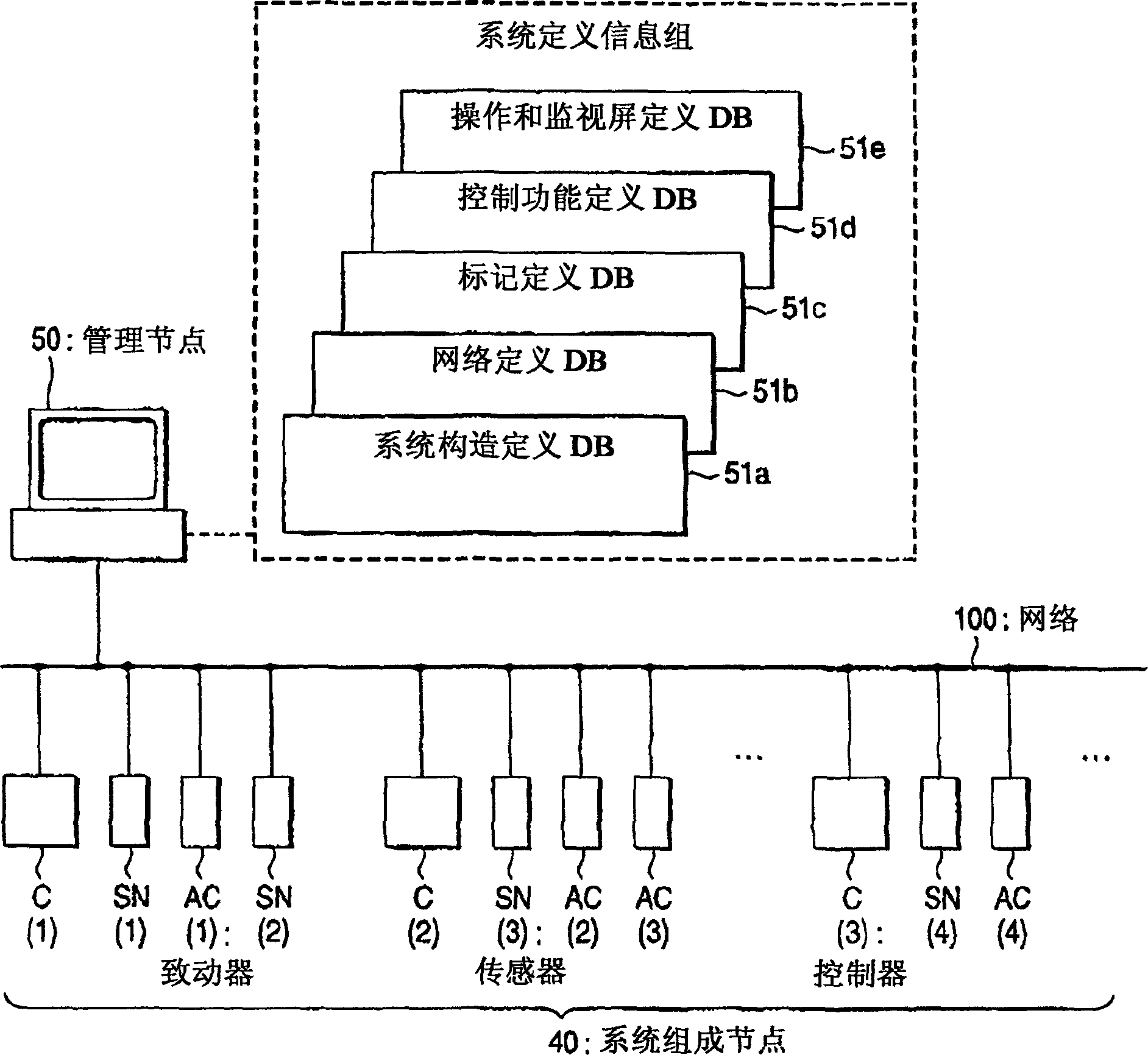
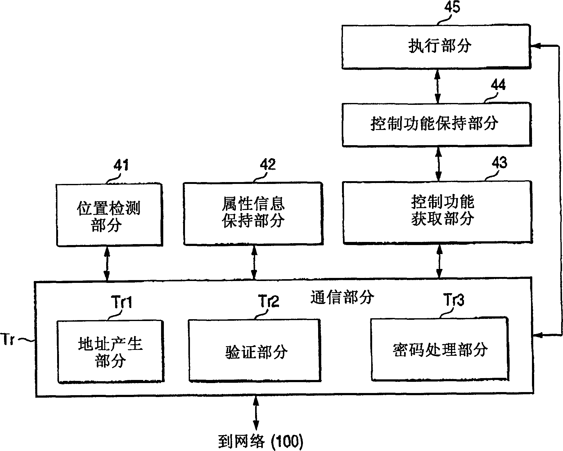
[0075] figure 2 is a structural diagram showing the first embodiment of the present invention. image 3 is a block diagram showing the structure of the system constituent node 40 . Figure 4 is a block diagram showing the configuration of the management node 50 . and figure 1 The same part in Figures 2 to 4 are denoted by the same reference numerals and will not be discussed again. exist Figures 2 to 4 In, instead of the controllers 20 to 22, the sensors 30, and the actuator 31, the controllers C(1) to C(3), the sensors SN(1) to SN(4), and the actuators AC(1 ) to AC (4) connected to network 100 (in figure 2 In , it is exemplified that 3 controllers, 4 sensors, and 4 actuators are connected, but any number of controllers, sensors, and actuators may be connected). Here, controllers C( 1 ) to C( 3 ), sensors SN( 1 ) to SN( 4 ), and actuators AC( 1 ) to AC( 4 ) are referred to as system constituent nodes 40 . and figure 1 Unlike the devices shown in , the system const...

no. 2 example

[0130] Figure 6 is a structural diagram showing a second embodiment of the present invention. and Figures 2 to 4 The same part in Figure 6 are denoted by the same reference numerals and are not discussed nor shown in the figures. Switching hubs SH1 to SH3 each having a plurality of ports are provided for the network 100 . The switching hubs SH1 to SH3 are provided between the network 100 and the system constituent nodes 40 . Sensors SN(1) to SN(4) and actuators AC( 1) to AC(4) are connected to the ports of the same switching hub SH1 to SH3. Each of the switching hubs SH1 to SH3 has an address table for holding the addresses of the system constituent nodes 40 connected to the ports. Furthermore, each port of the switching hubs SH1 to SH3 has a bridge mode in which a bridge function is provided.

[0131] The operation of this device is as follows:

[0132] Figure 6 The operation of the device shown in the figure 2 The operations of the devices shown in are exactly...

no. 3 example

[0136] Figure 7 is a diagram showing the structure of the third embodiment of the present invention and showing an example of applying the present invention to BA. and Figures 2 to 4 The same part in Figure 7 are denoted by the same reference numerals and will not be discussed again. exist Figure 7 In , instead of controllers C(1) to C(3), sensors SN(1) to SN(4), and actuators AC(1) to AC(4), in Figure 7 Controllers C(4) to C(6), sensors SN(5) to SN(7), and actuators AC(5) to AC(8) are provided in and connected to the network. Sensors SN ( 5 ) to SN ( 7 ), controllers C ( 4 ) to C ( 6 ), and actuators AC ( 5 ) to AC ( 8 ) constitute a system node 40 . For example, the sensors SN(5) to SN(7) are respectively an authentication sensor, a human body sensor, and a temperature sensor, and the actuators AC(5) and AC(8) are respectively the gates of an unshown door. Electronic locks and an air conditioner, and actuators AC(6) and AC(7) are lighting equipment.

[0137] The ...


PUM


Abstract

A system comprises a plurality of system component nodes each of which has a communication part that, when connected to a network, produces a unique global address and that transmits the produced global address, its attribute information and its positional information to the network; and an management node that manages the control of the whole control system. The management node has a communication part, a storage part for storing definition information; a display part for displaying an operating / monitoring window; a definition information generating part for generating the definition information from the global address, attribute information and positional information and for storing the generated definition information into the storage part; a window generating part for causing, based on the definition information stored in the storage part, the operating / monitoring window to be displayed; and a control function providing part for outputting, to the communication part, information in which the operations of the system component nodes have been defined.

Description

technical field [0001] The present invention relates to a control system established through a network, and more particularly, the present invention relates to a control system in which the system configuration can be changed in a short time. Background technique [0002] Control systems are available in systems of various sizes, from large control systems known as IA (Industrial Automation) (e.g. for the control and monitoring of factories) to medium-sized control systems known as BA (Building Automation) (e.g. , control and monitoring of air conditioning, lighting equipment, etc. in buildings), to small control systems called LA (laboratory automation) (for example, for a small number (several to dozens) of machine control and monitoring). [0003] This control system displays various information required for the control and operation system on the display screen of the display part of the management node used to manage the control of the entire control system, and if an ...

Claims


Application Information

Patent Timeline
Patent Type & Authority Applications(China)
IPC IPC(8): G05B23/02G06F13/00G05B19/042
CPCG05B19/042G05B2219/21028
Inventor 富田俊郎星哲夫
Owner YOKOGAWA ELECTRIC CORP
Why Eureka
Try Eureka