Viscous fluid application method

A viscous fluid and coating device technology, which is applied in the direction of surface coating liquid devices, coatings, electric solid devices, etc., can solve the problem of reduced design freedom, increased space occupation of the coating head, and decreased coating positioning accuracy And other issues

Inactive Publication Date: 2007-04-11
PANASONIC CORP
View PDF0 Cites 11 Cited by
  • Summary
  • Abstract
  • Description
  • Claims
  • Application Information

AI Technical Summary

Problems solved by technology

[0014] However, in the conventional viscous fluid application device, since the application head in which the supply part and the application part are integrated moves in the X direction, the Y direction, and the Z direction to perform the application operation, if the cartridge capacity is increased, When the applicator head is stopped, a large inertial force acts on the applicator head, so the positioning accuracy of the applicator decreases
Furthermore, the space occupation rate of the applicator head increases, and since it moves in the center of the viscous fluid applicator, the design of the viscous fluid applicator is greatly restricted, and the degree of freedom in design is reduced.

Method used


Image

  • Viscous fluid application method
  • Viscous fluid application method
  • Viscous fluid application method

Examples


Embodiment Construction

[0117] Next, a viscous fluid application device according to an embodiment of the present invention will be described with reference to the drawings.

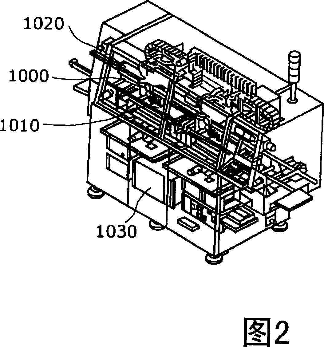
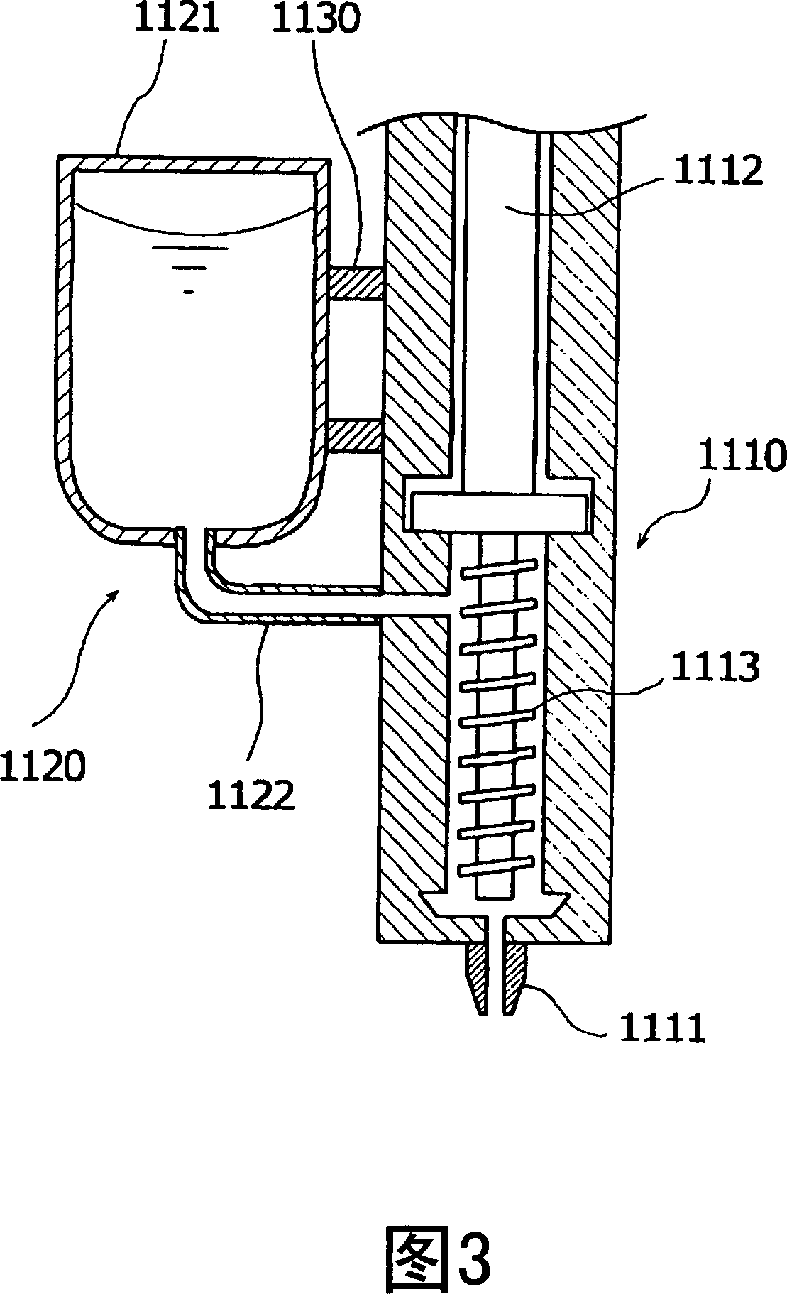
[0118] FIG. 4 is an external view of a viscous fluid application device according to this embodiment, and FIG. 5 is a diagram for explaining the structure of the viscous fluid application device.

[0119] The viscous fluid coating device of this embodiment includes: a coating head 100 for coating a viscous fluid on a substrate 140a; and a first shaft portion 110 (for example, an X-axis portion) for moving the coating head 100 in the first axial direction. Positioning; the second shaft part 120 (such as the Y-axis part), carries out the mobile positioning of the coating head 100 on the second shaft direction perpendicular to the first shaft direction; the third shaft part 130 (such as the Z-axis part), performs coating The movement and positioning of the application head 100 in the third axis direction perpendicular to the plane...


PUM


Abstract

A viscous fluid application device capable of increasing production efficiency of a semiconductor package without worsening positional accuracy in application and without reducing the degree of freedom in design. The device has an application head (100) having an application section (101) for applying a viscous fluid to a substrate (140a) and a supply section (102) for supplying the viscous fluid to the application section (101), an X-axis section (110), a Y-axis section (120), a Z-axis section (130), a substrate conveyance section (140), a head height detection sensor (150), and a control section (160). When the application section (101) moves in the Y-direction, the supply section (102) moves in the Y-direction in conjunction with the movement of the application section (101), and when the application section (101) moves in the X- and Y-directions, the supply section (102) stays still independent of the movement of the application section (101).

Description

technical field [0001] The present invention relates to a viscous fluid coating device, and more particularly to a viscous fluid coating device used in the manufacturing process of semiconductor packages. Background technique [0002] In high-speed semiconductor devices, flip-chip technology is used for electrical connection between semiconductor chips such as diodes, transistors, ICs (Integrated Circuits), and LSIs (Large Scale Integrations), and circuits formed on substrates on which the semiconductor chips are mounted. As the structure of the semiconductor package formed using the flip-chip technique, there are a mask-mounted type and a non-mask-mounted type. The hood-mounted type is suitable for semiconductor packages that contain high-frequency semiconductor chips that generate a large amount of heat, and the non-hood-mounted type is suitable for semiconductor packages that contain low-frequency semiconductor chips that generate less heat. [0003] FIG. 1 is a cross-se...

Claims


Application Information

Patent Timeline
IPC IPC(8): B05D3/00B05C5/00H01L21/56
CPCH01L2224/16225H01L2224/73204H01L2224/73253H01L2924/16152
Inventor 中达八郎饭塚章市川岩壁下朗冈本健二
Owner PANASONIC CORP
Why Eureka
Try Eureka