Hand-held machine tool

A hand-held machine tool, work area technology, applied in manual planing, manufacturing tools, hand-operated planing equipment, etc., can solve problems such as poor mechanical stability and chemical stability

Inactive Publication Date: 2007-06-13
ROBERT BOSCH GMBH
View PDF0 Cites 6 Cited by
  • Summary
  • Abstract
  • Description
  • Claims
  • Application Information

AI Technical Summary

Problems solved by technology

[0004] Textile filters have disadvantages due

Method used


Image

  • Hand-held machine tool

Examples


Embodiment Construction

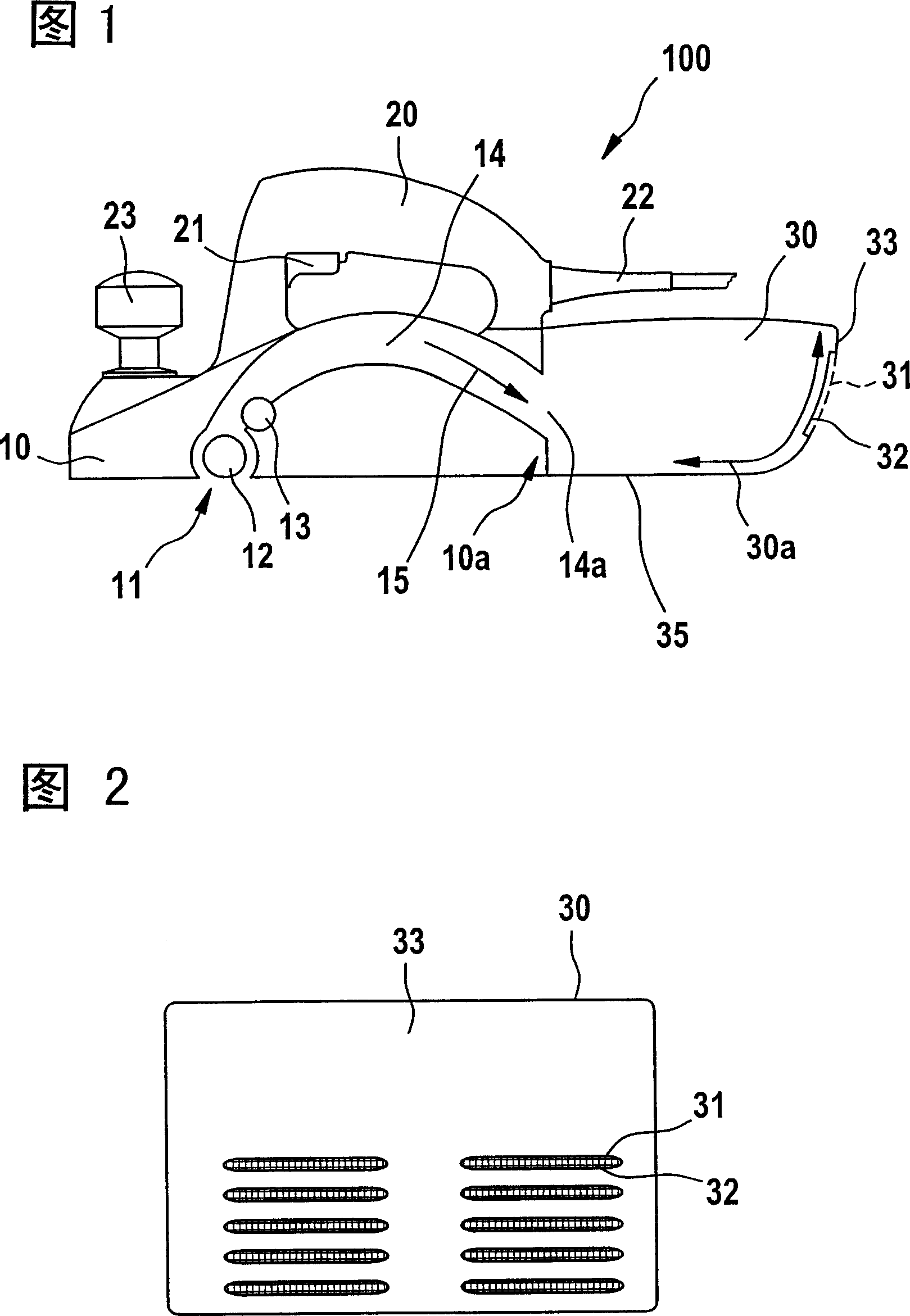
[0020] FIG. 1 schematically shows a hand planer 100 in longitudinal section. The hand planer comprises a housing 10 with a handle 20 , a power cable 22 , a switch 21 for switching the hand planer 100 on and off and a rotary switch 23 for adjusting the cutting depth.

[0021] A guide channel 14 is provided in the housing 10 , in which swarf and / or abrasive particles are guided away from the working area of ​​the hand planer 100 . The guide channel 14 extends longitudinally from the working area 11 through the hand planer 100 and is open to the rear, whereby an open end 14 a of the guide channel for ejecting chips is arranged in the rear region of the housing 10 10a. The guide channel 14 is arched across an electric motor (not shown) arranged transversely to the guide channel 14 .

[0022] Arranged in the working area 11 is a roller-shaped knife shaft 12 for cutting chips, in particular of woody material, which is driven via a drive belt by the electric motor of the hand-held ...


PUM


Abstract

A hand-held machine tool comprises a housing 10 with a guide duct for conducting shavings and/or abrasive particles away from an operating region. A collecting container for the shavings and/or abrasive particles is connected to the guide duct, having at least one opening for conducting away air from the collecting container. The opening in the collecting container is at least partially covered by a retaining element made of metal. Preferably the retaining element has a net, gauze, mesh, knit or lattice structure. The tool may be a planing machine.

Description

technical field [0001] The invention relates to a hand-held power tool. Background technique [0002] Hand-held power tools, in particular hand-held planers, are known which are provided with a guide channel for ejecting chips and / or abrasive particles. In this case, the guide channel is integrated in the housing of the hand-held power tool and opens out, for example, in the rear region of the housing. A collection container for swarf and / or abrasive particles can be connected to the guide channel. The hand power tool can include a blower unit or a suction unit, which generates an air flow in the guide channel in order to guide the swarf and / or abrasive particles out of the working area of ​​the hand power tool and transport them into the collection container. [0003] If the collecting container is an essentially rigid, gas-impermeable part, for example made of plastic, ventilation openings are provided in the receiving container. These vent holes may be larger than the ...

Claims


Application Information

Patent Timeline
IPC IPC(8): B25F5/00B25F5/02B27C1/10B23D9/00B24B23/00
CPCB27C1/10
Inventor 加博尔·帕普约瑟夫·杜达什
Owner ROBERT BOSCH GMBH
Why Eureka
Try Eureka