Fixing device for acoustic emission test sensors for rock damage testing

a technology fixing device, which is applied in the direction of measurement device, scientific instruments, instruments, etc., can solve the problems of increasing the difficulty of analyzing the test, increasing the difficulty of acoustic emission test sensor contact, and increasing the pressure of adhesive tape on the sensor, so as to improve the convenience of the test machin

Active Publication Date: 2018-07-10
SICHUAN UNIV
View PDF5 Cites 2 Cited by
  • Summary
  • Abstract
  • Description
  • Claims
  • Application Information

AI Technical Summary

Benefits of technology

[0006]In view of the above-described problems, it is one objective of the invention to provide a fixing device for acoustic emission test sensors for rock damage testing to ensure that centers of acoustic emission sides of the sensors pass through a diameter of a circular test piece or a center of a rectangular test piece and are consistent with the positions set by control software so as to improve efficiency, accuracy, and authenticity of the test.
[0016]The four installation mechanisms which can automatically and axially adjust positions of the installation bases are pairwise arranged on the loop-shaped fixing frame on the same section plane in two directions which are perpendicular to each other. The installation mechanism ensures that the acoustic emission test sensor disposed in the installation base always contacts the centers of the end faces of the sensor and that the installation positions of the sensors are consistent with the positions set by the control program. That is, the centers of the end faces of the four pairwise and symmetrically installed acoustic emission test sensors just pass through the diameter of the cylindrical test piece or the section center of the rectangular test piece. Thus, not only is the test information acquired from the test of the same test piece as much as possible, but also the position of the centers of the end faces of the sensors are consistent with the positions set in the control program during the installation and the test of the test piece, thus ensuring efficiency, accuracy and authenticity of the test. The fixing device of the invention ensures that the installation positions of the sensors are consistent with the positions set by the program and that the sensors are always disposed at the preset positions during the process of smearing coupling agent and the centers of the end faces of the sensors and the test piece are in a good coupling state.
[0017]The installation mechanisms of the invention are adapted to automatically and axially adjust positions of the installation bases. The springs are sleeved on the sliding bars between the installation bases and the inner wall of fixing frame, so that the end face of the sensors tightly contact the surface of the test piece, the stresses imposed on the acoustic emission test sensors are not increased during the radial swelling of the test piece in the test, and the sensors are under consistent stress in the test of the same batch of test pieces. The invention can not only reduce pseudo signals' influence on test results but also extend the service life of the acoustic emission test sensor. As for the fixing device disclosed in the prior art, since two parallel cantilever rods for fixing two acoustic emission test sensors are connected with each other by a connecting rod, the connecting rod is arranged on one side of the connecting rod when two acoustic emission test sensors are arranged on the test piece; and when the test piece is damaged abruptly in the test, the whole structure formed by the fixing device and the two acoustic emission test sensors swing towards the side where the connecting rod is disposed and then the side may run into the loading frame of the testing machine to damage the sensors and reduce test accuracy. Since the fixing device of the invention has an integrated structure and is nested outside the test piece, the fixing device suspends in the air when the test piece is damaged abruptly, thus preventing the fixing device from running into the testing machine and protecting the sensors more effectively.
[0018]During the whole test from loading of the test piece to the damage of the test piece, the shape of the test piece changes all the time. In the fixing device in the prior art, the two arm rods for arranging sensors change from the initial parallel state into a splay state, which lowers effectiveness of the coupling of the sensor transverse plane center and the test piece center and influences test accuracy. The sensors of the invention are arranged on the integrated rigid loop-shaped fixing frame by installation bases and installation mechanisms. During the process of test piece deformation, the sliding bars which are fixed on and connected with the sensors can stretch out and draw back freely in the guide tubes which serve as installation bases. Due to the springs sleeved on the sliding bars, the test sensors and the test pieces are always in the best coupling state. The invention overcomes the shortcomings of fixing devices in the prior art. The fixing device of the invention also has the advantages of the prior art (excluding universal arbitrary adjustment).
[0020]The fixing frame of the invention is a dismountable fixing frame formed by integrating the two semi-circular or rectangular frame members via the fixing structures. Thus, the acoustic emission test sensors can be installed before or after the installation of the test piece in the testing machine, and different installation modes are applicable for different test pieces, thereby improving the convenience of the testing machine.

Problems solved by technology

However, adhesive tape tends to increase the pressure on the sensors and even damage them, and rubber band cannot guarantee good contact between the acoustic emission test sensors and samples.
For these reasons, conventional fixing methods have the following shortcomings: (1) the fixing methods cannot ensure accurate positioning of the sensors; (2) the fixing methods produce signal noise and artifacts, which increases the difficulty in analyzing the test results; and (3) the fixing methods are of limited use with deformation test sensors.

Method used


Image

  • Fixing device for acoustic emission test sensors for rock damage testing
  • Fixing device for acoustic emission test sensors for rock damage testing
  • Fixing device for acoustic emission test sensors for rock damage testing

Examples


example 1

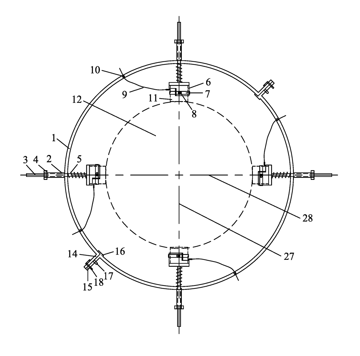
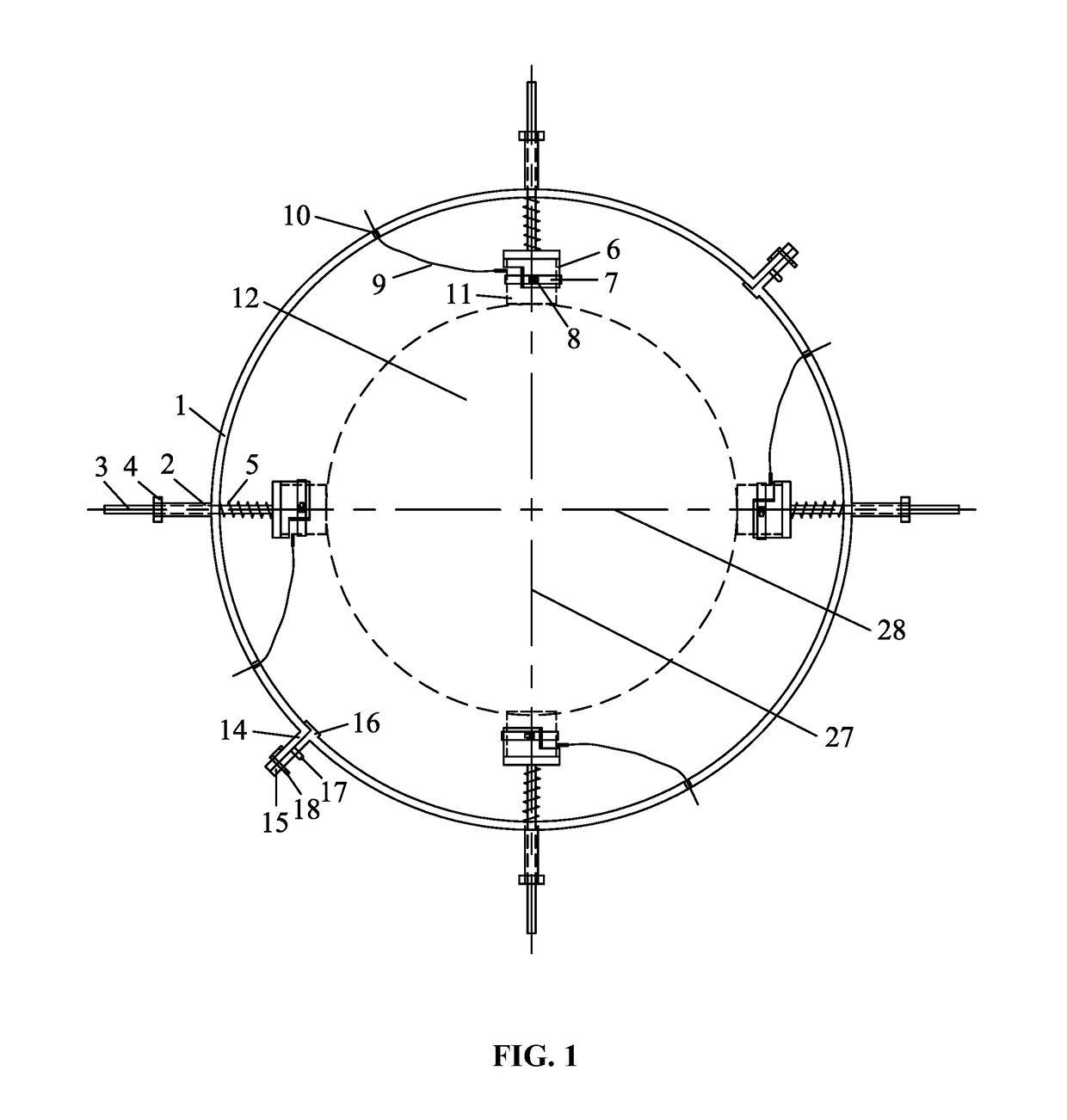
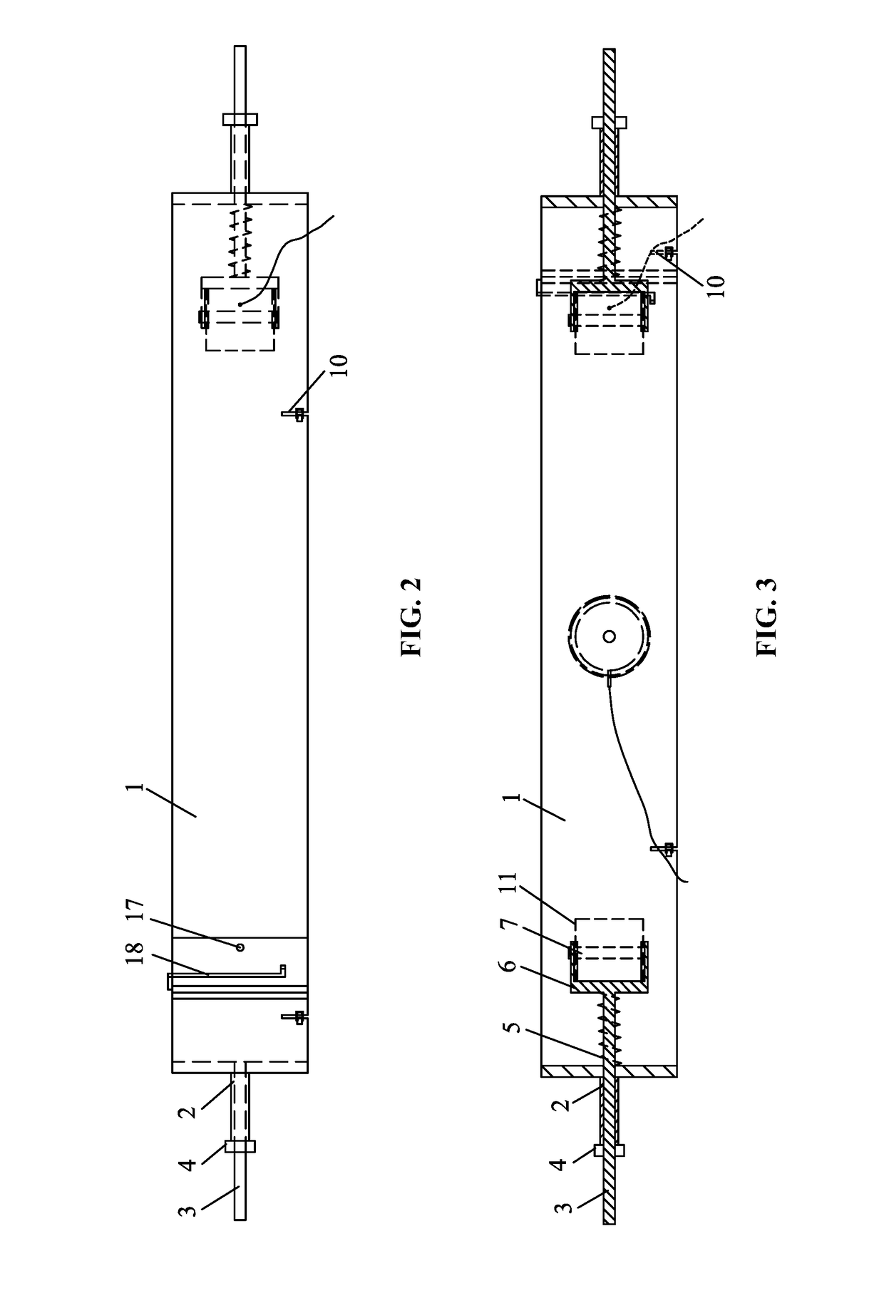
[0039]A fixing device for acoustic emission test sensors for rock damage testing is provided in this example, as shown in FIGS. 1, 2, 3, 5-1, 5-2, 6, 7, 8-1, 8-2, and 8-3. The fixing device is adapted to test a cylindrical rock sample as a test piece. The fixing device comprises: an integrated fixing frame 1 assembled by two semi-circular frame members via fixing structures, installation bases 6 operating to accommodate acoustic emission test sensors 11, fixing assemblies operating to fix the acoustic emission test sensors 11 in the installation bases 6, and installation mechanisms operating to install the installation bases 6 on the fixing frame 1. As shown in FIGS. 8-1, 8-2 and 8-3, each fixing structure comprises: a first connection lug 14 and a second connection lug 15 arranged on joint ends of the two semi-circular frame members, a spigot 16 arranged on the joint end of one semi-circular frame member for connecting and limiting the joint end of the other semi-circular frame mem...

example 2

[0053]A structure of a fixing device for acoustic emission test sensors for rock damage testing is shown in FIGS. 4 and 7, and the test piece is a rectangular rock sample. The structure of the fixing device in this example is the same as that of Example 1 except that: (1) the fixing frame 1 is an integrated rectangular loop-shaped fixing frame 1 assembled by a first frame part 25 and a second frame part 26 via fixing structures; and (2) in the fixing assemblies configured to fix the acoustic emission test sensors 11 in the corresponding installation bases 6, the locking structures for lock the split ring springs 7 adopt bolt-nut locking structures.


PUM

PropertyMeasurementUnit
angleaaaaaaaaaa
angleaaaaaaaaaa
diameteraaaaaaaaaa

Abstract

A fixing device for acoustic emission test sensors for rock damage testing, the device including: a fixing frame; installation bases operating to accommodate the acoustic emission test sensors, respectively; fixing assemblies operating to fix the acoustic emission test sensors in the installation bases; and installation mechanisms operating to arrange the installation bases on the fixing frame. The fixing frame is an assembled loop-shaped frame and includes between two and four frame members and corresponding fixing structures; and the frame members are assembled into an integrated loop-shaped frame by the fixing structures. Each of the installation bases is a cylinder structure. The cylinder structure includes: a cavity corresponding to an outer edge of each of the acoustic emission test sensors, and a wall including a gap for leading out wires of each sensor.

Description

CROSS-REFERENCE TO RELATED APPLICATIONS[0001]Pursuant to 35 U.S.C. § 119 and the Paris Convention Treaty, this application claims the benefit of Chinese Patent Application No. 201510067706.4 filed Feb. 9, 2015, the contents of which are incorporated herein by reference.BACKGROUND OF THE INVENTION[0002]Field of the Invention[0003]The invention relates to a fixing device for acoustic emission test sensors for damage testing of material samples.[0004]Description of the Related Art[0005]Conventionally, acoustic emission test sensors are fixed by adhesive tape or rubber band. However, adhesive tape tends to increase the pressure on the sensors and even damage them, and rubber band cannot guarantee good contact between the acoustic emission test sensors and samples. For these reasons, conventional fixing methods have the following shortcomings: (1) the fixing methods cannot ensure accurate positioning of the sensors; (2) the fixing methods produce signal noise and artifacts, which increas...

Claims


Application Information

Patent Timeline
Patent Type & Authority Patents(United States)
IPC IPC(8): G01N29/14G01N29/22
CPCG01N29/14G01N29/223G01N2291/0232
Inventor LIU, JIANFENGXIE, HEPINGJU, YANGPEI, JIANLIANGXU, HUININGWANG, LU
Owner SICHUAN UNIV
Why Eureka
Try Eureka