Fixing device for acoustic emission test sensors for rock damage testing

a technology of acoustic emission test and fixing device, which is applied in the direction of measurement device, scientific instruments, instruments, etc., can solve the problems of increasing the difficulty of analyzing the test, the inability of rubber bands to guarantee good contact between acoustic emission test sensors and samples, and the tendency of adhesive tape to increase the pressure on the sensor, etc., to improve the efficiency, accuracy, and authenticity of the test

Active Publication Date: 2016-08-11
SICHUAN UNIV
View PDF6 Cites 5 Cited by
  • Summary
  • Abstract
  • Description
  • Claims
  • Application Information

AI Technical Summary

Benefits of technology

[0006]In view of the above-described problems, it is one objective of the invention to provide a fixing device for acoustic emission test sensors for rock damage testing to ensure that centers of end faces of the sensors

Problems solved by technology

However, adhesive tape tends to increase the pressure on the sensors and even damage them, and rubber band cannot guarantee good contact between the acoustic emission test sensors and samples.
For these reasons, conventional fixing methods have the following shortcomings:

Method used


Image

  • Fixing device for acoustic emission test sensors for rock damage testing
  • Fixing device for acoustic emission test sensors for rock damage testing
  • Fixing device for acoustic emission test sensors for rock damage testing

Examples


example 1

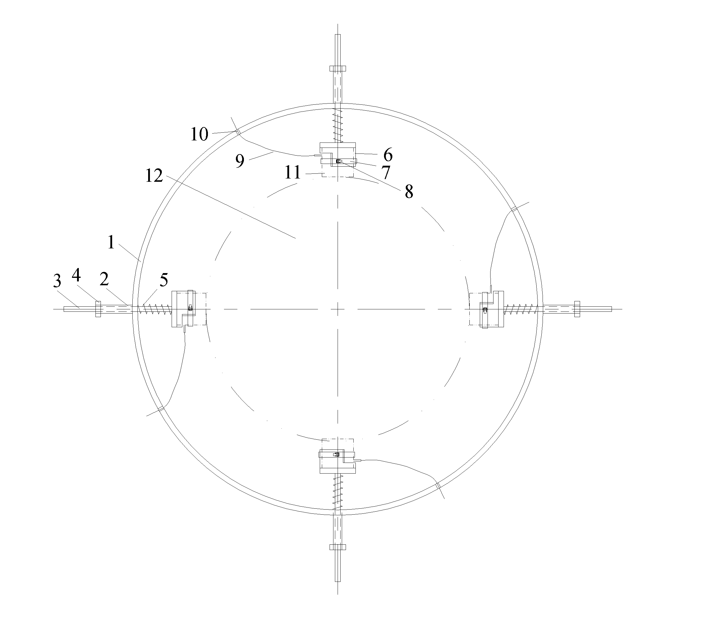
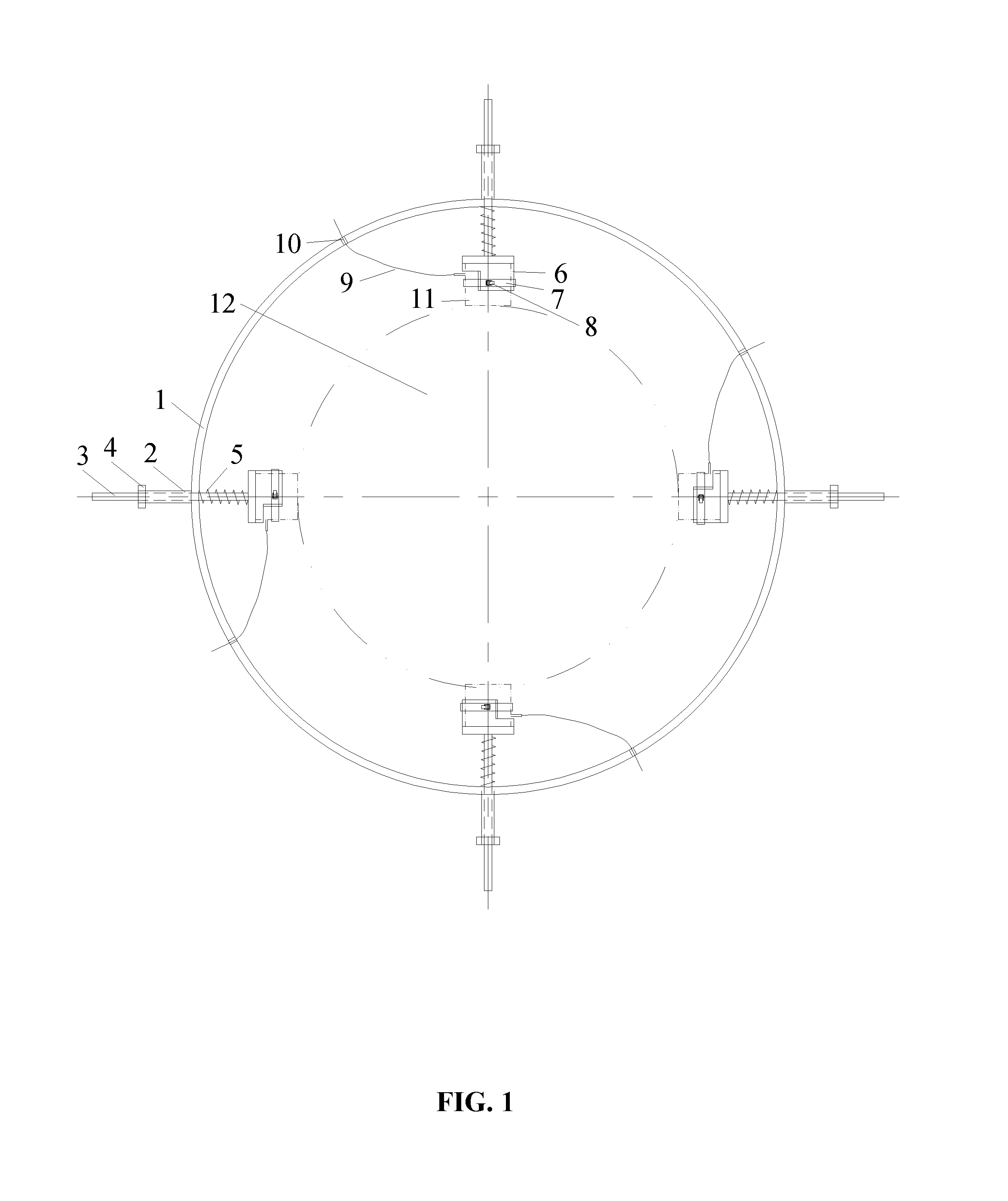
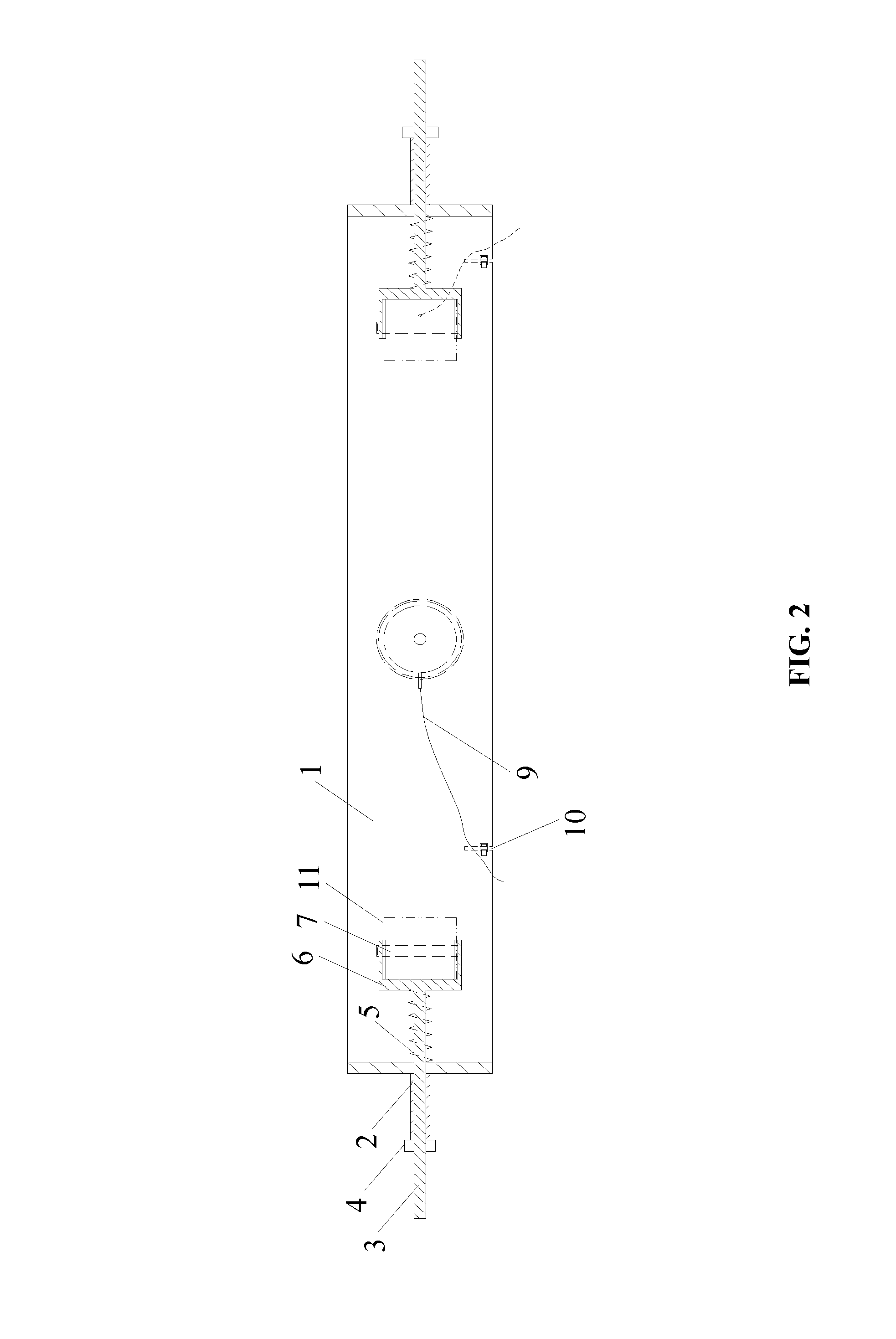
[0029]A fixing device for acoustic emission test sensors for rock damage testing is provided in this example, as shown in FIGS. 1, 2, 4, 5, and 6. The fixing device is adapted to test a cylindrical rock sample as a test piece. The fixing device comprises: an integrated circular loop-shaped fixing frame 1, installation bases 6 operating to accommodate acoustic emission test sensors 11, fixing assemblies operating to fix the acoustic emission test sensors 11 in the installation bases 6, and installation mechanisms operating to install the installation bases 6 on the fixing frame 1. Each of the installation bases is a cylinder with a closed end, and a cavity of the cylinder matches an outer edge of the acoustic emission test sensor 11. A gap for leading out wires of the sensor is disposed on the cylinder wall, and an angle of the gap is 90°. Each of the fixing assemblies configured to fix the acoustic emission test sensor 11 in the installation base 6 is formed by a split ring spring 7...

example 2

[0036]A structure of a fixing device for acoustic emission test sensors for rock damage testing is shown in FIGS. 2, 3, 4, 5, and 7, and the test piece is a rectangular rock sample. The structure of the fixing device in this example is the same as that of Example 1 except that: (1) the fixing frame 1 is an integrated rectangular loop-shaped fixing frame 1; and (2) in the fixing assemblies configured to fix the acoustic emission test sensors 11 in the corresponding installation bases 6, the locking structures for lock the split ring springs 7 adopt bolt-nut locking structures.


PUM


Abstract

A fixing device for acoustic emission test sensors for rock damage testing, the device including: a fixing frame, installation bases operating to accommodate the acoustic emission test sensors, respectively, fixing assemblies operating to fix the acoustic emission test sensors in the installation bases, and installation mechanisms operating to install the installation bases on the fixing frame. The fixing frame is an integrated loop-shaped frame. Each of the installation bases is a cylinder structure which includes: a cavity corresponding to an outer edge of each of the acoustic emission test sensors, and a wall including a gap for leading out wires of each sensor. The installation mechanisms are adapted to automatically and axially adjust positions of the installation bases. The installation mechanisms are four in number. The four installation mechanisms are disposed on a same section plane of the fixing frame and every two installation mechanisms are oppositely disposed.

Description

CROSS-REFERENCE TO RELATED APPLICATIONS[0001]Pursuant to 35 U.S.C. §119 and the Paris Convention Treaty, this application claims the benefit of Chinese Patent Application No. 201510068149.8 filed Feb. 9, 2015, the contents of which are incorporated herein by reference.BACKGROUND OF THE INVENTION[0002]1. Field of the Invention[0003]The invention relates to a fixing device for acoustic emission test sensors for damage testing of material samples.[0004]2. Description of the Related Art[0005]Conventionally, acoustic emission test sensors are fixed by adhesive tape or rubber band. However, adhesive tape tends to increase the pressure on the sensors and even damage them, and rubber band cannot guarantee good contact between the acoustic emission test sensors and samples. For these reasons, conventional fixing methods have the following shortcomings: (1) the fixing methods cannot ensure accurate positioning of the sensors; (2) the fixing methods produce signal noise and artifacts, which in...

Claims


Application Information

Patent Timeline
IPC IPC(8): G01N29/14
CPCG01N2291/0232G01N29/14G01N29/223
Inventor LIU, JIANFENGXIE, HEPINGJU, YANGWANG, LUXU, HUININGZUO, JIANPINGXU, YANGMENGDIZOU, HANGZHOU, ZHIWEIZHUO, YUE
Owner SICHUAN UNIV
Why Eureka
Try Eureka