Driver circuit able to monitor usage of a surge protection arrangement

a driver circuit and surge protection technology, applied in emergency protection arrangements for limiting excess voltage/current, pulse generators, pulse techniques, etc., can solve the problems of fuse breaking, high risk of electronic devices, lightning and other power turbulence, etc., and achieve the effect of less component/footprint and low cos

Active Publication Date: 2018-08-14
SIGNIFY HLDG BV
View PDF14 Cites 0 Cited by
  • Summary
  • Abstract
  • Description
  • Claims
  • Application Information

AI Technical Summary

Benefits of technology

[0010]It would be advantageous to have a surge counting function of low cost and less component / footprint. To better address this concern, the proposed invention is defined by the claims.
[0016]This driver circuit is able to monitor how many surge events (in the mains input) have taken place. In this way, the usage of a surge protection arrangement can be monitored, so that the lifetime of such a surge protection arrangement can be monitored. The monitoring does not require complex additional circuitry, since it can be implemented simply using analysis of the existing pulse width control signal generated by the existing pulse width controller of the switch mode power converter. The example of the invention thus provides a new surge counter method for a switch mode power supply unit, such as used in an LED driver. By monitoring the PWM signal in an LED driver, the surge event can be detected without needing a current transformer. The cost of the surge counter is thus low and almost no additional parts are needed in the driver.
[0024]It would be advantageous to have a more robust and accurate solution in identifying the surge from other power abnormal conditions such as spike, noise, or long term overpower. In another example, the monitor is for detecting the surge event from changes in the pulse width and / or duty cycle over time, and comprises a monitor circuit for detecting a surge event based on the pulse width reducing to a narrow pulse width, or the duty cycle reducing to a low duty cycle from a wide pulse (i.e. with longer pulse width or larger duty cycle than for the narrow pulse), remaining with the narrow pulse characteristics for a time period falling within a range (which can be considered as the short duration as noted above) and then returning to the wide pulse. This is used to detect a series of narrow pulses, and which series lasts for a particular duration.
[0037]The pulse counter logic circuit may be used to detect a specific sequence of detection pulses, for example a sequence of 1 s having a length (i.e. number of the pulses) corresponding to a time period falling within the pre-set range. The above function can be easily implemented in the PWM controller of the switch power converter thus the cost is low and does not need to add extra components.

Problems solved by technology

The surge current caused by lightning and other power turbulences is a high risk for electronic devices, such as LED drivers and telecommunications devices, which incorporate semiconductor components.
The lifetime of a metal oxide varistor is however limited and relates to the number of times it has been used to bypass a surge event and the current it has bypassed.
When the device has failed, usually it will cause a fuse to break and the AC input is disconnected.
These solutions are effective but they are costly.
They also need additional installation space.
This solution is not suitable for small power units such as an LED driver.

Method used


Image

  • Driver circuit able to monitor usage of a surge protection arrangement
  • Driver circuit able to monitor usage of a surge protection arrangement
  • Driver circuit able to monitor usage of a surge protection arrangement

Examples


Embodiment Construction

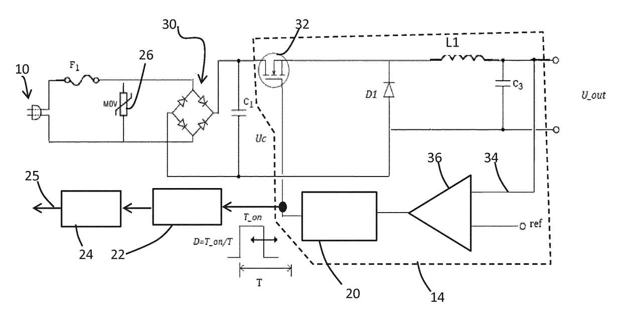
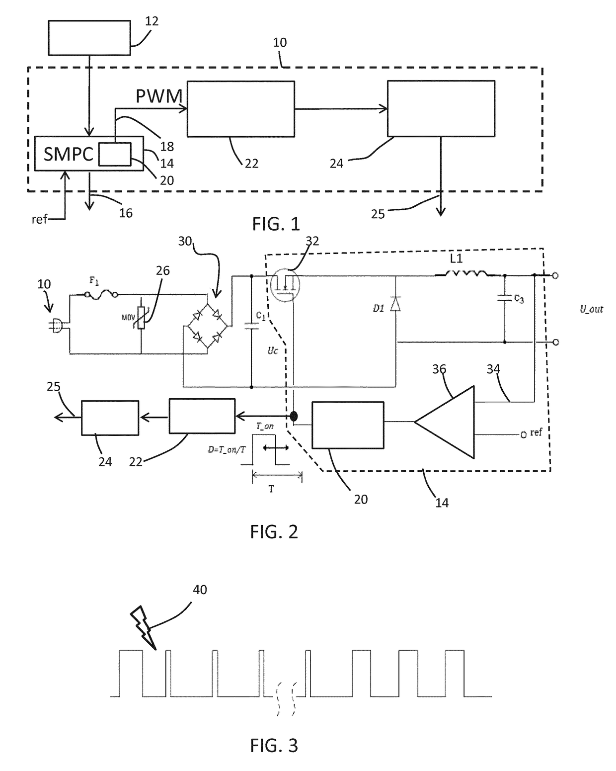
[0061]The invention provides a driver circuit comprising a mains input and a switch mode power converter for delivering an output derived from the mains input by switching using a pulse width modulation signal. The switch mode power converter comprises a pulse width controller for controlling the pulse width and / or duty cycle of the pulse width modulation signal. A monitor is used for monitoring the pulse width of the pulse width modulation signal and for detecting a surge event from the pulse width and / or duty cycle.

[0062]FIG. 1 shows in schematic form an example of the driver circuit 10 of the invention.

[0063]The circuit 10 is supplied by a mains supply 12 and includes a switch mode power converter SMPC for delivering an output 16 derived from the mains input by switching using a pulse width modulation signal 18. This pulse width modulation signal 18 is generated by a pulse width controller 20 for controlling the pulse width of the pulse width modulation signal.

[0064]A monitor is ...


PUM


Abstract

A driver circuit comprises a mains input and a switch mode power converter for delivering an output derived from the mains input by switching using a pulse width modulation signal. The switch mode power converter comprises a pulse width controller for controlling the pulse width of the pulse width modulation signal. A monitor is used for monitoring the pulse width of the pulse width modulation signal and for detecting a surge event from the pulse width, wherein the monitor is for detecting the surge event from changes in the pulse width and / or duty cycle over time, and comprises a monitor circuit for detecting a surge event based on the pulse width and / or duty cycle reducing to correspond to a first pulse from a second pulse, remaining at the first pulse for a time period falling within a first threshold range and then returning to the second pulse, wherein the width of the first pulse is narrower than the second pulse.

Description

CROSS-REFERENCE TO PRIOR APPLICATIONS[0001]This application is the U.S. National Phase application under 35 U.S.C. § 371 of International Application No. PCT / EP2016 / 051828, filed on Jan. 26, 2016 which claims the benefit of Chinese Patent Application No. PCT / CN2015 / 072139, filed on Feb. 3, 2015 and European Patent Application No. 15159714.3, filed on Mar. 18, 2015. These applications are hereby incorporated by reference herein.FIELD OF THE INVENTION[0002]This invention relates to the use of surge protection arrangements in driver circuits, and in particular relates to the counting of surge events to enable the lifetime of such surge protection arrangements to be monitored.BACKGROUND OF THE INVENTION[0003]It is well known to use surge protection devices to protect electronic circuits from damage during surge events.[0004]The surge current caused by lightning and other power turbulences is a high risk for electronic devices, such as LED drivers and telecommunications devices, which in...

Claims


Application Information

Patent Timeline
Patent Type & Authority Patents(United States)
IPC IPC(8): H05B33/08H02H9/00H03K3/017H05B44/00H05B45/50
CPCH02H9/005H05B33/0887H05B33/0818H03K3/017H02H9/042H05B45/50H05B45/37H02H3/04H02H9/041Y02B20/30H05B45/3725H05B45/375
Inventor CHEN, HONGCHEN, HONGXIN
Owner SIGNIFY HLDG BV
Why Eureka
Try Eureka