Short-range optical amplification module, spectacles, helmet and VR system

a technology of optical amplification and short-range, applied in the field of optical apparatus, can solve the problems of not meeting the requirements of compact and ultra-thin structure, and achieve the effects of small overall thickness, wide field angle, and large optical amplification

Active Publication Date: 2019-01-22
SHENZHEN DLODLO NEW TECHNOLOGY CO LTD
View PDF33 Cites 2 Cited by
  • Summary
  • Abstract
  • Description
  • Claims
  • Application Information

AI Technical Summary

Benefits of technology

[0005]Embodiments of the invention provide a short-range optical amplification module, thereby the objects may be attained that the short-range optical amplification module can be used in a small-size VR device and the VR device has a wide field angle, a large eyebox and high-quality imaging effect. The present invention further provides a pair of spectacles, a helmet and a VR system.
[0023]It may be seen from the above technical solutions that, in the short-range optical amplification module according to the invention, parameter refining on the effective focal length of the reflection surface of the third lens which is the core part that influences the optical amplification effect enables the module to keep a small overall thickness while obtaining a large optical amplification effect, so that the module can be applied in a small-size VR device; moreover, the VR device can realize a wide field angle, a large eyebox and high-quality imaging effect, and hence a better user experience.

Problems solved by technology

Since each optical device takes a certain amount of installation space, the size and volume of an optical amplification module consisting of a plurality of optical devices are usually both very large, which especially cannot meet the compact and ultrathin structure requirement for an intelligent Virtual Reality (VR).

Method used


Image

  • Short-range optical amplification module, spectacles, helmet and VR system
  • Short-range optical amplification module, spectacles, helmet and VR system
  • Short-range optical amplification module, spectacles, helmet and VR system

Examples


embodiment 1

[0072

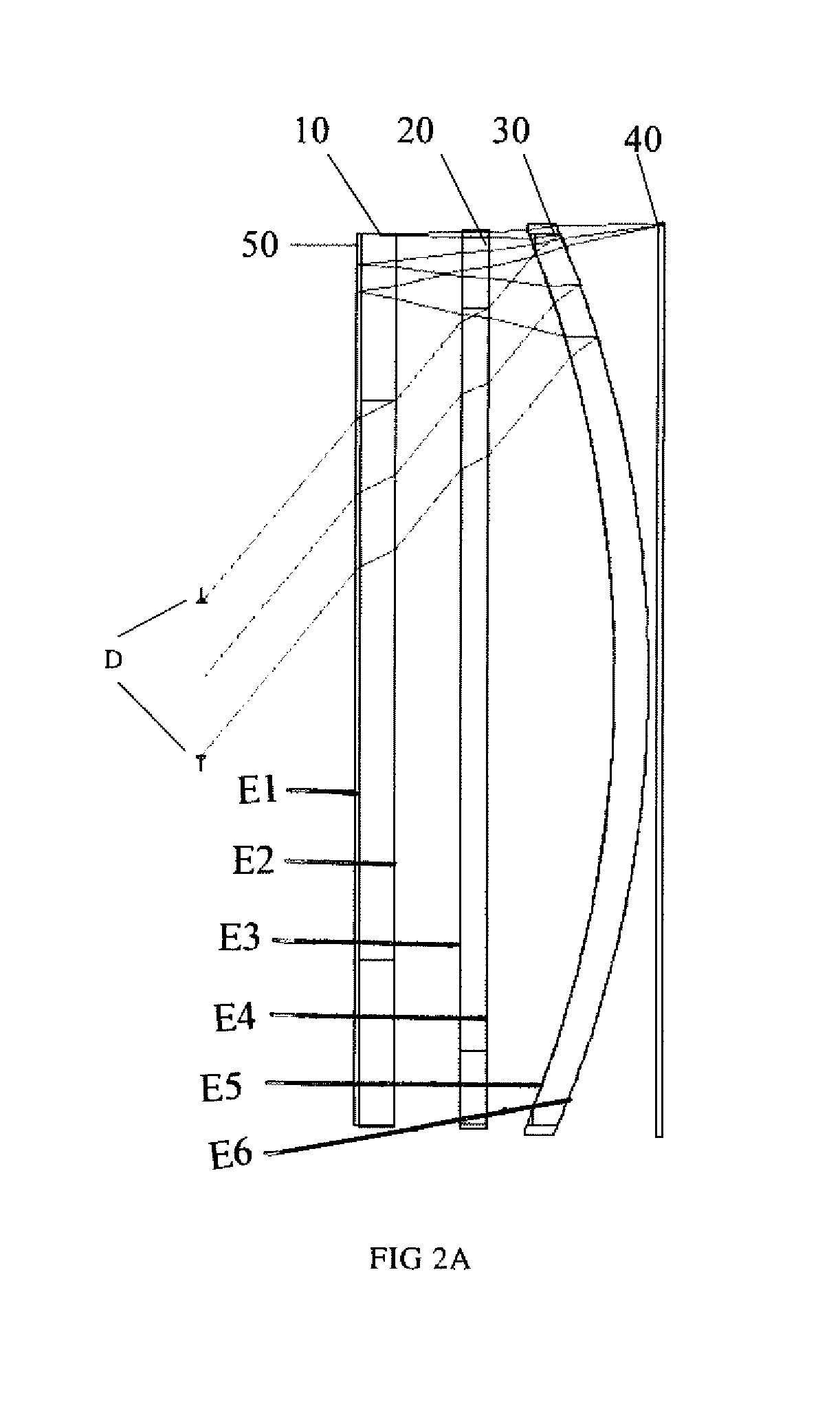
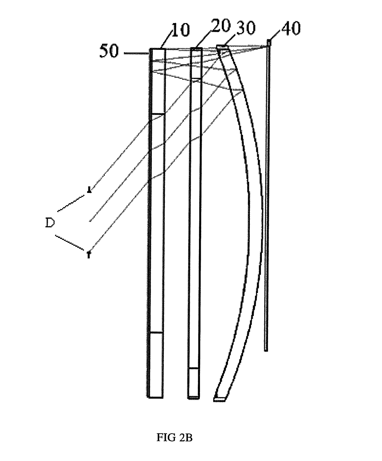
[0073]As shown in FIG. 2, in the short-range optical amplification module, the reflection surface-containing focal length f3 of the third lens 30 is designed as equal to the system focal length F.

[0074]The specific design parameters of the first lens 10, the second lens 20 and the third lens 30 are as shown in Table 1:

[0075]

SurfTypeCommentRadius ThicknessGlassDiameterConicOBJSTANDARDInfinityInfinity00 1PARAXIAL—09—STOSTANDARDInfinity990 3STANDARDInfinity0.3BK730.181560 4STANDARDInfinity030.530680 5STANDARDInfinity2H-LAK5A30.530680 6STANDARDInfinity3.91699632.573390 7STANDARDInfinity1.5H-ZF1341.792070 8STANDARDInfinity 7.4522843.21420 9STANDARD−682H-LAK1049.68908010STANDARD−66.19397−2MIRROR51.8908011STANDARD−68051.39615012STANDARDInfinity−1.5H-ZF1351.52681013STANDARDInfinity3.91699651.57252014STANDARDInfinity−2H-LAK5A51.78493015STANDARDInfinity051.84964016STANDARDInfinity−0.3BK751.84964017STANDARDInfinity0.3MIRROR51.86038018STANDARDInfinity051.87111019STANDARDInfinity2H-LAK5A51....

embodiment 2

[0081

[0082]As shown in FIG. 6, in the short-range optical amplification module, the reflection surface-containing focal length f3 of the third lens 30 is designed as 1.37F (F is the system focal length).

[0083]The specific design parameters of the first lens 10, the second lens 20 and the third lens 30 are as shown in Table 3:

[0084]

TABLE 3SurfTypeCommentRadiusThicknessGlassDiameterConicOBJSTANDARDInfinityInfinity001 PARAXIAL—07—STOSTANDARDInfinity970 3STANDARDInfinity0.3BK726.092640 4STANDARDInfinity026.421120 5STANDARDInfinity2H-K9L310 6STANDARD−89.758730.1310 7STANDARD84.662671H-ZF1132.20 8STANDARD54.388121.55822231.340 9STANDARD160.63424D-LAK7032.2010STANDARD−54.28037−4MIRROR32.2011STANDARD160.63421.55822232.2012STANDARD54.38812−1H-ZF1131.34013STANDARD84.66267−0.132.2014STANDARDInfinity−2H-K9L31015STANDARDInfinity031016STANDARDInfinity−0.3BK732.2017STANDARDInfinity0.3MIRROR32.2018STANDARDInfinity032.2019STANDARDInfinity2H-K9L31020STANDARD−89.758730.131021STANDARD84.662671H-ZF1132....

embodiment 3

[0090

[0091]As shown in FIG. 10, in the short-range optical amplification module, the reflection surface-containing focal length f3 of the third lens 30 is designed as 1.5F (F is the system focal length).

[0092]The specific design parameters of the first lens 10, the second lens 20 and the third lens 30 are as shown in Table 5:

[0093]

TABLE 5SurfTypeCommentRadiusThicknessGlassDiameterConicOBJSTANDARDInfinityInfinity00 1PARAXIAL—09—STOSTANDARDInfinity990 3STANDARDInfinity0.3BK730.181560 4STANDARDInfinity030.530680 5STANDARDInfinity4H-LAK5A30.530680 6STANDARD−126.36042.5182333.478650 7STANDARD252.96361.5H-ZF1341.408070 8STANDARD123.37011.70108143.192580 9STANDARD269.28465.5H-LAK1044.98185010STANDARD−101.0977−5.5MIRROR46.69545011STANDARD269.28461.70108146.59742012STANDARD123.3701−1.5H-ZF1346.49442013STANDARD252.9636−2.5182346.6367014STANDARD−126.3604−4H-LAK5A46.36075015STANDARDInfinity046.02962016STANDARDInfinity−0.3BK746.02962017STANDARDInfinity0.3MIRROR45.97037018STANDARDInfinity045.9111...


PUM

PropertyMeasurementUnit
focal lengthaaaaaaaaaa
distanceaaaaaaaaaa
distanceaaaaaaaaaa

Abstract

The present invention discloses a short-range optical amplification module, which includes, sequentially from the image side to the object side, a reflective polarizing plate, a first phase delay plate, a third lens and a second phase delay plate, wherein the short-range optical amplification module further includes a first lens and / or a second lens that are / is located on either side of any one of the reflective polarizing plate, the first phase delay plate, the third lens and the second phase delay plate. In the third lens, the optical surface adjacent to the second phase delay plate is a transflective optical surface; the reflection surface-containing focal length f3 of the third lens meets the following condition: 1F≤f3≤2F, wherein F is the focal length of the short-range optical amplification module. By performing parameter refining on the f3 that influences the optical amplification effect, the module can keep a small overall thickness while obtaining a large optical amplification effect and it can be applied in a small-size VR device, so that the VR device can realize a wide field angle, a large eyebox and high-quality imaging effect, and hence a better user experience.

Description

FIELD OF THE INVENTION[0001]The present invention relates to the technical field of optical apparatus, and in particular, to a short-range optical amplification module, spectacles, a helmet and a virtual reality (VR) system.BACKGROUND OF THE INVENTION[0002]At present, a short-range optical amplification modules has already been disclosed. In order to meet the imaging quality requirement, the module usually comprises a plurality of optical devices. As shown in FIG. 1, it includes, sequentially from the image side to the object side, a reflective polarizing plate 01, a first phase delay plate 02, a lens unit 03 and a second phase delay plate 04. In the lens unit 03, the optical surface adjacent to the second phase delay plate 04 is a transflective optical surface. In use, the optical image from the object side is transmissively amplified by the lens unit 03, then reflected by the reflective polarizing plate 01, and again amplified by the lens unit 03, and finally enters the human eye ...

Claims


Application Information

Patent Timeline
Patent Type & Authority Patents(United States)
IPC IPC(8): G02B27/28G06T19/00G06T3/40G06T3/00G02B27/00G02B27/10G02F1/01G02B5/30G02B27/01G02B27/02G02B27/09
CPCG02B27/0172G02B5/30G02B27/0012G02B27/01G02B27/10G02B27/28G06T3/0018G06T3/4053G06T19/006G02F1/01G02B27/286G02B5/3083G02B27/0025G02B27/0977G02B2027/0123
Inventor LI, GANGTANG, WEIPING
Owner SHENZHEN DLODLO NEW TECHNOLOGY CO LTD
Why Eureka
Try Eureka