Short-range optical amplification module, spectacles, helmet and VR system

a short-range, optical amplification module technology, applied in the field of optical apparatus, can solve the problems of inability to guarantee a good user experience, and achieve the effects of wide field angle, large optical amplification effect, and small overall thickness

Active Publication Date: 2018-07-10
SHENZHEN DLODLO NEW TECHNOLOGY CO LTD
View PDF16 Cites 3 Cited by
  • Summary
  • Abstract
  • Description
  • Claims
  • Application Information

AI Technical Summary

Benefits of technology

[0021]In the embodiments of the present invention, parameter refining on the first focal length f2 that influences the optical amplification effect enables the module to keep a small overall thickness while obtaining a large optical amplification effect, so that the VR device can achieve a wide field angle, a large eyebox, high-quality imaging effect, and hence a better user experience.

Problems solved by technology

However, the structure of the existing optical amplification module does not have an optimized design, thus it cannot be guaranteed that the above objects can be achieved in the whole range, that is, it cannot guarantee a good user experience.

Method used


Image

  • Short-range optical amplification module, spectacles, helmet and VR system
  • Short-range optical amplification module, spectacles, helmet and VR system
  • Short-range optical amplification module, spectacles, helmet and VR system

Examples


embodiment 1

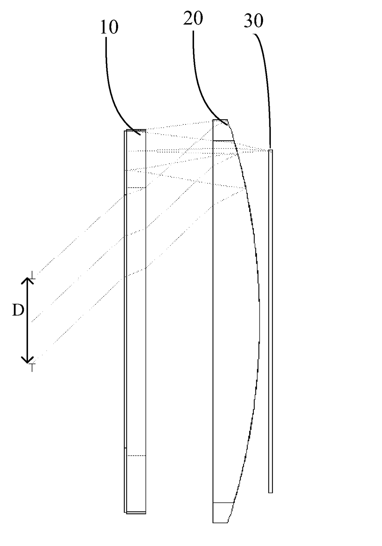
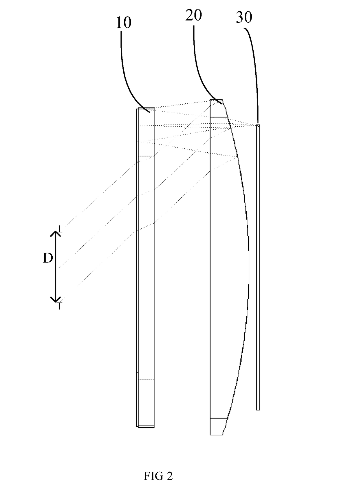
[0064]As shown in FIG. 2, in the short-range optical amplification module, the focal length f1 of the first lens is designed as infinity, and the first focal length f2 of the second lens 20 is designed as 1.2F (F is the system focal length), wherein:

[0065]The specific design parameters of the short-range optical amplification module are as shown in Table 1:

[0066]

SurfTypeRadiusThicknessGlassDiameterConicOBJSTANDARDInfinity−102.8883205.77660STOSTANDARDInfinity550 2STANDARDInfinity0.1028883PMMA14.757020 3STANDARDInfinity1.028883H-ZF52A14.866190 4STANDARDInfinity3.63005515.7104−32.99979 5STANDARDInfinity2.5H-QK122.79410 6STANDARD−42.3863−2.5MIRROR23.64590.8191897 7STANDARDInfinity−3.63005523.504520 8STANDARDInfinity−1.028883H-ZF52A22.54349−32.99979 9STANDARDInfinity−0.1028883PMMA22.39635010STANDARDInfinity0MIRROR22.37816011STANDARDInfinity0.1028883PMMA22.37816012STANDARDInfinity1.028883H-ZF52A22.35997013STANDARDInfinity3.63005522.21283−32.9997914STANDARDInfinity2.5H-QK121.2518015STANDAR...

embodiment 2

[0073]As shown in FIG. 6, in the short-range optical amplification module, the focal length f1 of the first lens is designed as 8.7F, and the first focal length f2 of the second lens 20 is designed as 1.6F (F is the system focal length), wherein:

[0074]The specific design parameters of the short-range optical amplification module are as shown in Table 3:

[0075]

SurfTypeRadiusThicknessGlassDiameterConicOBJSTANDARDInfinityInfinity00 1PARAXIAL—06—STOSTANDARDInfinity860 3STANDARDInfinity0.3BK7340 4STANDARDInfinity0340 5STANDARDInfinity1.5PMMA34−28.9321 6EVENASPH−55.029690.47709623431.73109 7EVENASPH215.7895.5PMMA343.135107 8STANDARD−53.02166−5.5MIRROR3431.73109 9EVENASPH215.789−0.477096234−28.932110EVENASPH−55.02969−1.5PMMA34011STANDARDInfinity034012STANDARDInfinity−0.3BK734013STANDARDInfinity0.3MIRROR34014STANDARDInfinity034015STANDARDInfinity1.5PMMA34016EVENASPH−55.029690.477096234−28.932117EVENASPH215.7895.5PMMA3431.7310918STANDARD−53.021660.5343.13510719STANDARDInfinity1BK721.15540IMAS...

embodiment 3

[0089]As shown in FIG. 10, in the short-range optical amplification module, the focal length f1 of the first lens is designed as 8.7F, and the first focal length f2 of the second lens 20 is designed as 1.89F (F is the system focal length), wherein:

[0090]The specific design parameters of the short-range optical amplification module are as shown in Table 6:

[0091]

SurfTypeRadiusThicknessGlassDiameterConicOBJSTANDARDInfinityInfinity00 1PARAXIAL—06—STOSTANDARDInfinity860 3STANDARDInfinity0.3BK7340 4STANDARDInfinity0340 5STANDARDInfinity2.5PMMA34−30.574 6EVENASPH−37.842981.06885534−33.0001 7EVENASPH25452.914.5PMMA3410.01056 8STANDARD−66−4.5MIRROR34−33.0001 9EVENASPH25452.91−1.06885534−30.57410EVENASPH−37.84298−2.5PMMA34011STANDARDInfinity034012STANDARDInfinity−0.3BK734013STANDARDInfinity0.3MIRROR34014STANDARDInfinity034015STANDARDInfinity2.5PMMA34016EVENASPH−37.842981.06885534−30.57417EVENASPH25452.914.5PMMA34−33.000118STANDARD−660.53410.0105619STANDARDInfinity1BK722.940170IMASTANDARDInfin...


PUM


Abstract

Disclosed are a short-range optical amplification module, spectacles, a helmet and a VR system. The amplification module includes a reflective polarizing plate, a first phase delay plate, a second lens and a second phase delay plate that are arranged in turn, and a first lens is further set on either side of any one of the reflective polarizing plate, the first phase delay plate, the second lens and the second phase delay plate; in the second lens, the optical surface adjacent to the second phase delay plate is a transflective optical surface; the first focal length f2 of the second lens meets the condition: 1.2F≤f2≤2F, wherein F is the system focal length of the optical amplification module. By performing parameter refining on the first focal length f2 that influences the optical amplification effect, the module can keep a small overall thickness while obtaining a large optical amplification effect, and the VR device can realize a good field angle, a large eyebox and a high-quality imaging effect, and hence a better user experience.

Description

FIELD OF THE INVENTION[0001]The present invention relates to an optical apparatus, and in particular, to a short-range optical amplification module, spectacles, a helmet and a VR system.BACKGROUND OF THE INVENTION[0002]In the structure of an existing optical amplification module, as shown in FIG. 1, it includes, sequentially from the image side to the object side, a reflective polarizing plate 01, a first phase delay plate 02, a lens unit 03 and a second phase delay plate 04. In the lens unit 03, the optical surface adjacent to the second phase delay plate 04 is a transflective optical surface. In use, the optical image from the object side is transmissively amplified by the lens unit 03, then reflected by the reflective polarizing plate 01, and again amplified by the lens unit 03, and finally enters the human eye via the reflective polarizing plate 01. Moreover, other lens units that do not influence the phase delay of light are further set on either side of any one of the reflecti...

Claims


Application Information

Patent Timeline
Patent Type & Authority Patents(United States)
IPC IPC(8): G09G5/00G02B27/09G06F3/01G02B27/01G02B27/28
CPCG02B27/0172G02B27/0101G02B27/0977G06F3/011G02B27/28G02B2027/0178G02B2027/0123G02B27/017G02B27/283G02B27/01
Inventor LI, GANGTANG, WEIPING
Owner SHENZHEN DLODLO NEW TECHNOLOGY CO LTD
Why Eureka
Try Eureka