Safety switch with lock-out device

a safety switch and lockout technology, applied in the direction of information technology support systems, electrical equipment, sustainable buildings, etc., can solve the problems of not making the switch suitable for applications, not ensuring the complete shielding of the switching unit in every situation, and lack of modularity of the switch, so as to prevent the intervention

Active Publication Date: 2019-03-26
PIZZATO ELETTRICA
View PDF3 Cites 0 Cited by
  • Summary
  • Abstract
  • Description
  • Claims
  • Application Information

AI Technical Summary

Benefits of technology

[0032]A further object is to provide a safety switch with lock-out device with high modularity and reconfigurability to be used both on doors with right closure and left closure, either of the hinged type or sliding type, without being necessary to vary the mounting of the switch.
[0033]Not least object of the present invention is to provide a safety switch with lock-out device which allows the closure of the protection even with the lock-out inserted, preventing in any case the reactivation of the system, and thus be used in applications for which it is important to have always the protection closed.
[0036]According to a peculiar feature of the invention said movable guard comprises a shielding element adapted to be interposed between said communication elements when said guard is in said active position for avoiding the passage of said signal and prevent the closure of said switching means.
[0043]In this way the accidental reset of the inactive position for the protection may be prevented in unsafe situations, such as for example in case of presence of an operator within the controlled perimeter, as it will be sufficient that the operator entering the perimeter inserts the locking means after activating the protection.
[0044]At the same time it will prevent that the locking means may be inserted with the lock-out device in the inactive position or in any intermediate position along the stroke of the device, thus preventing the intervention.

Problems solved by technology

Therefore, the protection action exerted by the two brackets is entrusted exclusively to the fact that the two units are kept spaced apart, but does not guarantee complete shielding of the switching unit in every situation.
As a consequence, this known switch does not prevent that there may be potential situations wherein there may still be communication between the two elements, even in a situation of open access.
Consequently, this condition does not makes the switch suitable for applications where it is necessary that the protection will remain closed even in the condition of the stopped plant, such as for example for refrigerators or other situations wherein it is important to preserve the environmental conditions inside the protected perimeter.
A further drawback is represented by the lack of modularity of the switch, whose configuration is such as to require different modes of mounting according to the type of closing of the door to which the switch is designed.
Still a further drawback, common to the known solutions of both the mechanical and electronic operating type, including those previously described, is represented by the fact that the positioning of the holes for the insertion of the locks is such that the latter can be inserted even when the lock-out device is not inserted or is inserted in only partially, so that it would be prevented from passing in the safe active position.

Method used


Image

  • Safety switch with lock-out device
  • Safety switch with lock-out device
  • Safety switch with lock-out device

Examples


first embodiment

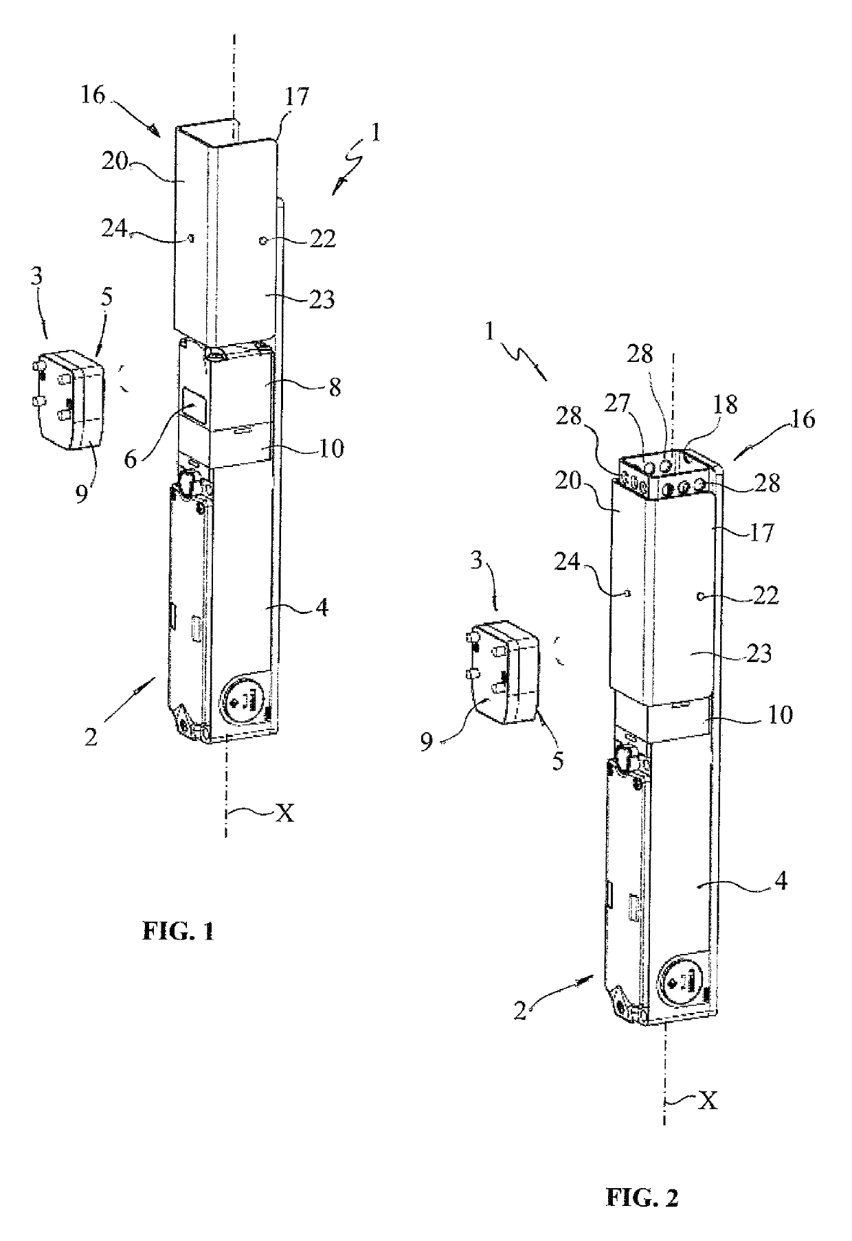
[0077]FIG. 1 shows the safety switch, generally indicated by 1, which essentially comprises a switching unit 2 adapted to be anchored to the fixed part of the structure and an operating unit 3 adapted to be anchored to the movable part of the structure. In a known manner the switching unit 2 comprises a box-shaped case 4 defining a longitudinal axis X and housing thereinside switching means adapted to be operatively connected to the power supply circuit of the system to be controlled for the opening / closing thereof and possibly to one or more further control and / or service circuits of the plant for controlling thereof.

[0078]The switching means are not visible from the annexed figures as being of the known type and may be designed according to any of the typical ways for this type of switches, without particular limitations.

[0079]In turn, the operating unit 3 comprises actuating means 5 adapted to interact with the switching means upon closing of the movable part on the fixed part to...

second embodiment

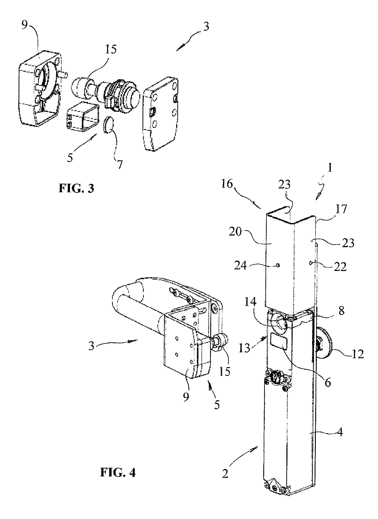
[0092]For example, the mushroom emergency button 12 may be positioned to project toward the inside of the protection so that it can be operated from the inside thereof to cause the stop of the plant in a dangerous situation, as in the case in which an operator remains within the safety perimeter following the closure of the protection with consequent starting of the plant. FIG. 4 shows the switch 1 which differs from that of FIG. 1 mainly in that it comprises centering means 13 associated to both units 2, 3 and adapted to allow an at least partial alignment between the first and second communication element 6, 7 at the time of closure of access.

[0093]In particular, the centering means 13 comprise a centering hole 14 made in the head 8 of the switching unit 2, upperly to the antenna 6, and a centering pin 15 projecting from the box-like shell 9 of the operating unit 3, upperly to the transmitter 7.

[0094]The hole 14 and the centering pin 15 will have the task of aligning in a precise ...

third embodiment

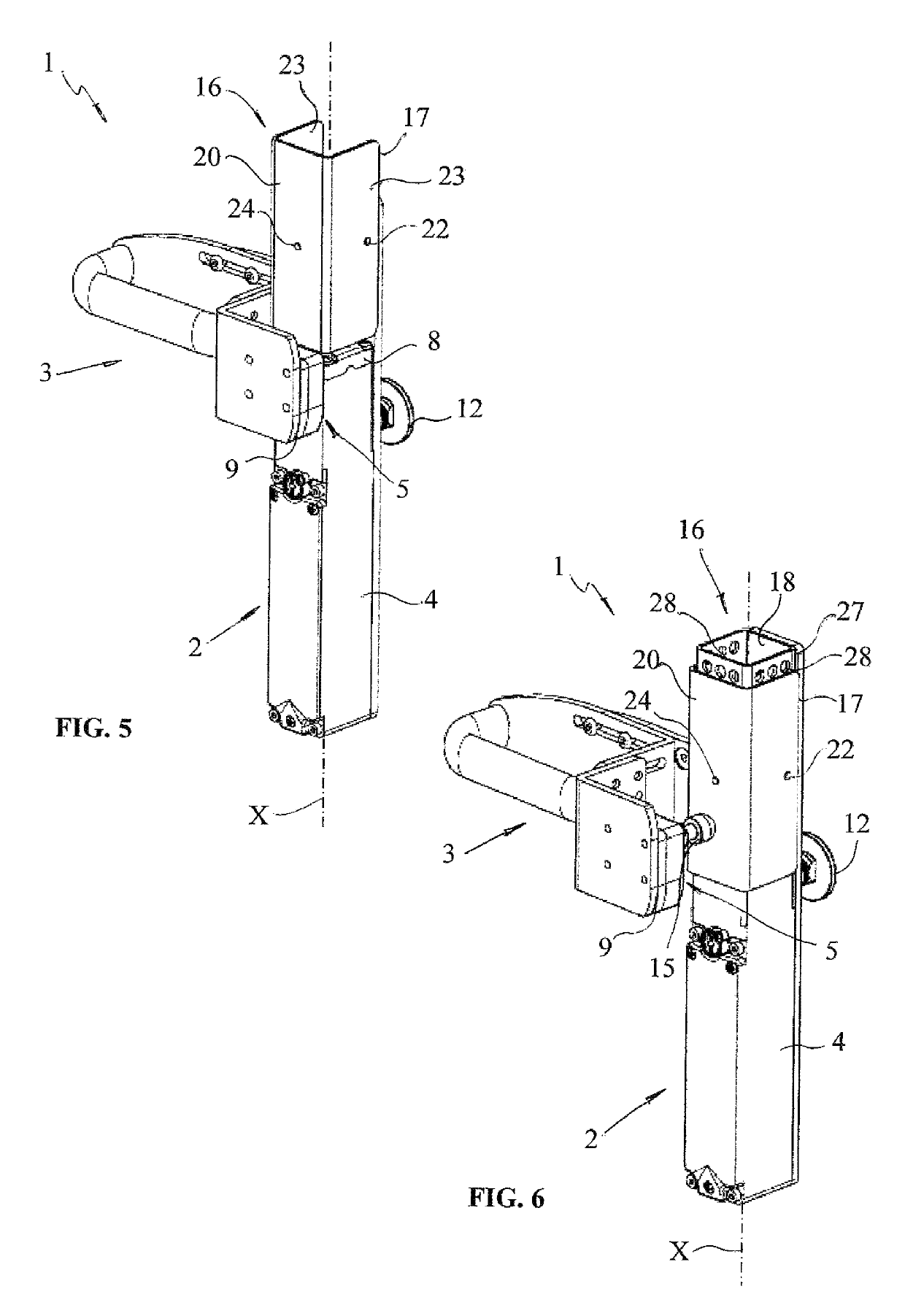
[0116]FIG. 15 shows a third embodiment for the switch 1 substantially similar to that of FIG. 4 and from which it differs, as well as for the presence of two emergency controls 11, 12, for the fact that both the head 8 and the intermediate module 10 of the switch unit 2 are mounted on the case 4 so as to rotate about an axis of rotation R substantially parallel to the longitudinal axis X.

[0117]The head 8 and the intermediate module 10 may rotate separately from each other and the rotation of the head 8 will have mainly the object to vary the angular orientation of the first communication element 6, possibly in a manner integral with the centering hole 14, to keep it always facing the second communication element 7, the position of which depends instead on the open mode of the movable part.

[0118]FIG. 16 shows the same switch 1 of FIG. 15 with the lock-out device 16 inserted but not locked. FIG. 17 shows the switch 1 of FIG. 1 according two additional assembly modes in which the head ...


PUM


Abstract

A safety switch with a lock-out device including a switching unit, switching elements and actuating elements. The switching elements and the actuating elements are electronic and are respectively associated with a first communication element and a second communication element adapted to remote communicating therebetween by a signal and to allow the switching elements to discriminate the presence of an operating unit close to the switching unit. The switching unit includes a movable guard having a shielding element adapted to interpose itself between the communication elements when the guard is into the active position to avoid the transmission of the signal and the closing of the switching elements.

Description

TECHNICAL FIELD[0001]The present invention finds application in the field of electric safety devices and in particular relates to a safety switch with lock-out device designed to be applied to perimeter protection structures for industrial machines or plants.STATE OF THE ART[0002]As known, the perimeter protection structures for industrial plants or machines have to be properly controlled in order to prevent access inside the perimeter when the machine or plant is working and avoid that the machine or plant may be inadvertently actuated in unsafe conditions, for example with workers still within the perimeter.[0003]To this end, the perimeter protection structures are suitably equipped, at certain accesses, of one or more safety switches connected to the plant and designed to interrupt the power supply upon opening of the controlled access.[0004]These switches should also be configured to avoid any further dangerous situation that might possibly be determined due to inadvertent behav...

Claims


Application Information

Patent Timeline
Patent Type & Authority Patents(United States)
IPC IPC(8): H01H27/00F16P3/08
CPCF16P3/08H01H27/007Y04S20/14Y02B90/224H01H2300/032Y02B90/20
Inventor PIZZATO, MARCOZONTA, SIMONE
Owner PIZZATO ELETTRICA
Why Eureka
Try Eureka