Detection device

a detection device and detection technology, applied in the field of optical devices, to achieve the effect of good detection quality

Active Publication Date: 2020-02-04
GINGY TECH
View PDF8 Cites 2 Cited by
  • Summary
  • Abstract
  • Description
  • Claims
  • Application Information

AI Technical Summary

Benefits of technology

[0006]The invention provides a detection device with good detection quality.

Problems solved by technology

However, the challenge that currently needs to be overcome is to add the function of detecting physiological states into the current fingerprint identification device without affecting the original function of the fingerprint identification device while keeping the function of detecting physiological states operating accurately.

Method used


Image

  • Detection device
  • Detection device
  • Detection device

Examples


Embodiment Construction

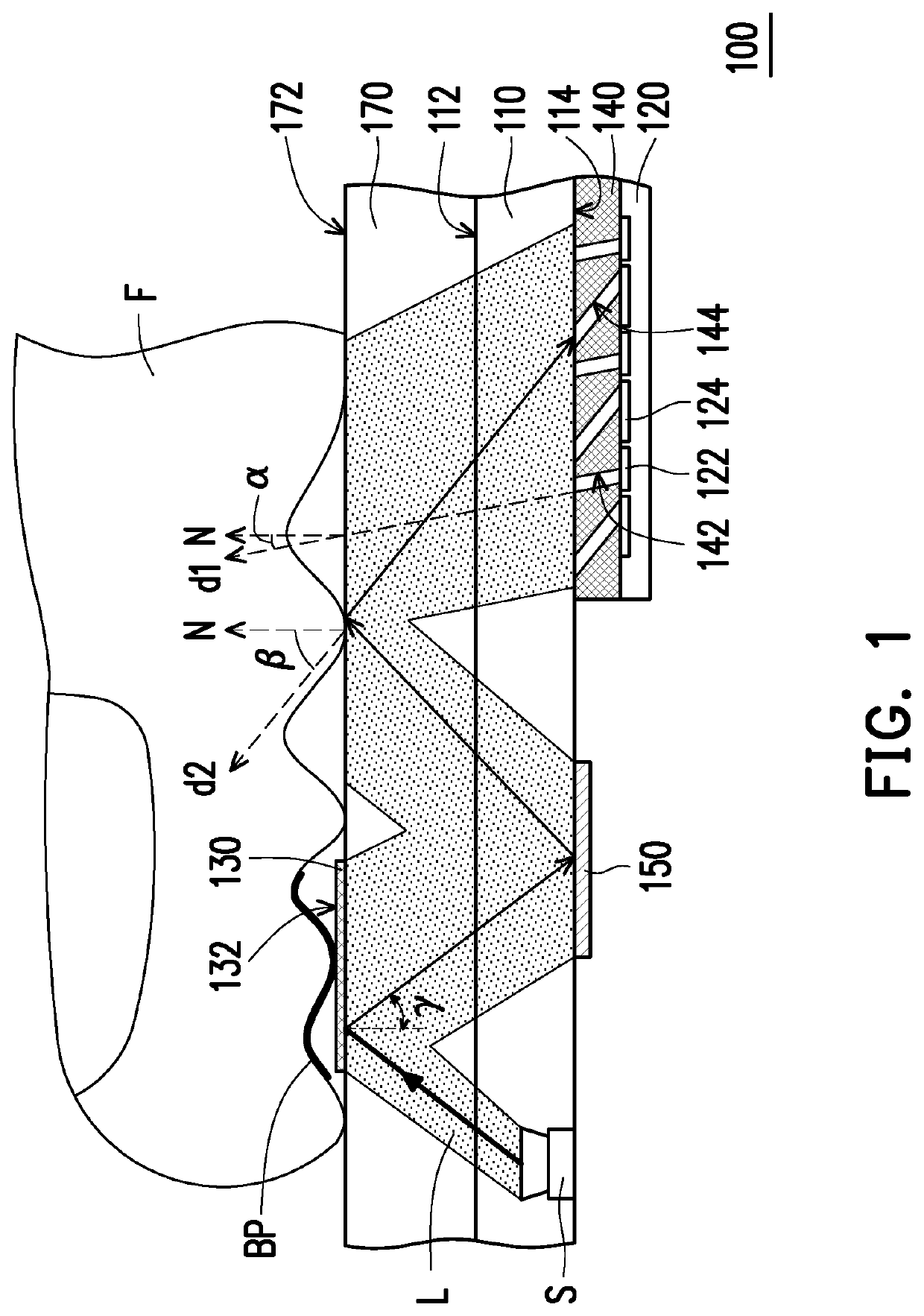
[0024]FIG. 1 is a schematic cross-sectional view of a detection device according to an embodiment of the invention. With reference to FIG. 1, a detection device 100 includes a light guide element 110, a sensing element 120, a surface plasma resonance layer 130 and a spatial filter element 140. The light guide element 110 has a top surface 112 and a bottom surface 114 opposite to the top surface 112. In this embodiment, the light guide element 110 is an optical adhesive layer, for example. However, the invention is not limited thereto. In another embodiment, the light guide element 110 may also be a light transmitting substrate, and a material thereof may be selected from glass, polymethylmethacrylate (PMMA), polycarbonate (PC), or other suitable light transmitting materials. In this embodiment, the detection device 100 may include a light source S for emitting a light beam L. In this embodiment, the light source S may be embedded in the light guide element 110 (e.g., an optical adhe...


PUM

PropertyMeasurementUnit
included angleaaaaaaaaaa
resonant angleaaaaaaaaaa

Abstract

A detection device including a light guide element, a sensing element, a surface plasma resonance layer and a spatial filter element is provided. The light guide element has a top surface and a bottom surface opposite to the top surface. The sensing element is disposed beside the bottom surface of the light guide element. The surface plasma resonance layer is disposed on the top surface of the light guide element and is adapted to receive biopolymers. The spatial filter element is disposed between the bottom surface of the light guide element and the sensing element. The spatial filter element has a plurality of first light channels and a plurality of second light channels. The plurality of first light channels extend in a first direction, the plurality of second light channels extend in a second direction, and the first direction and the second direction are intersected. A normal direction of the top surface of the light guide element and the second direction form an included angle β, and the included angle β corresponds to a resonant angle γ of the surface plasma resonance layer.

Description

CROSS-REFERENCE TO RELATED APPLICATION[0001]This application claims the priority benefits of U.S. provisional application Ser. No. 62 / 574,222, filed on Oct. 19, 2017, U.S. provisional application Ser. No. 62 / 620,985, filed on Jan. 23, 2018, and China application serial no. 201820286719.X, filed on Mar. 1, 2018. The entirety of each of the above-mentioned patent applications is hereby incorporated by reference herein and made a part of this specification.BACKGROUND OF THE INVENTIONField of the Invention[0002]The disclosure relates to an optical device, and particularly relates to a detection device.Description of Related Art[0003]Biometric identification is applied to detect and identify faces, irises, retinas, veins and fingerprints. Since each person has unique fingerprints, and since the fingerprints do not change due to age or physical health, fingerprint identification devices have currently become the most popular biometric devices. Based on different sensing methods, the finge...

Claims


Application Information

Patent Timeline
Patent Type & Authority Patents(United States)
IPC IPC(8): G01N21/552G02B6/122G01N21/59B60R25/25
CPCG01N21/554B60R25/252G02B6/1226G01N2021/5903A61B5/1172G01N21/553A61B5/0077A61B5/14507A61B5/14532A61B5/6826A61B2562/0233G06V40/1324
Inventor WU, JEN-CHIEHWANG, CHIUNG-HANLIN, PATRICK
Owner GINGY TECH
Why Eureka
Try Eureka