Labor-saving stapler

a stapler and labor-saving technology, applied in the field of labor-saving staplers, can solve the problems of insufficient function of elastic sheets, more labor-intensive stapler use, and complex structure of staplers, and achieve the effect of convenient operation and increased energy accumulation

Active Publication Date: 2021-07-20
APEX MFG
View PDF32 Cites 1 Cited by
  • Summary
  • Abstract
  • Description
  • Claims
  • Application Information

AI Technical Summary

Benefits of technology

[0007]The major object of the present invention is to provide a labor-saving stapler which is labor-saving and can increase energy accumulated to make operation more convenient.

Problems solved by technology

In actual use, this type of stapler has a more complex structure, and it is more labor-consuming to use the stapler.
When the connection rod is abraded due to long-term use, the striker may be released earlier, the elastic sheet may not be fully functioned, and the nail may not be struck precisely.
Secondly, if the striker and the connection rod change positions slightly due to an error during production or being hit by a force, the striker may be released in different timings, and the striker may be non-releasable or be released earlier.
If a user uses the stapler continuously and quickly, the striker tends to strike downward before the nail moves to the correct position; therefore, the nail is squeezed abnormally to block an outlet of the nail and cause damage.
This can cause abrasion, damage and deformation of lever, spring and protrusion of the housing, and unstable of force of the spring for striker.
Furthermore, the striker is near the nail outlet when the energy-accumulating mechanism is in the releasing state, which can affect the staples due to contact of the striker with the staples as the striker is raised.

Method used


Image

  • Labor-saving stapler
  • Labor-saving stapler
  • Labor-saving stapler

Examples


Embodiment Construction

[0014]The present invention will be clearer from the following description when viewed together with the accompanying drawings, which show, for purpose of illustrations only, the preferred embodiment in accordance with the present invention.

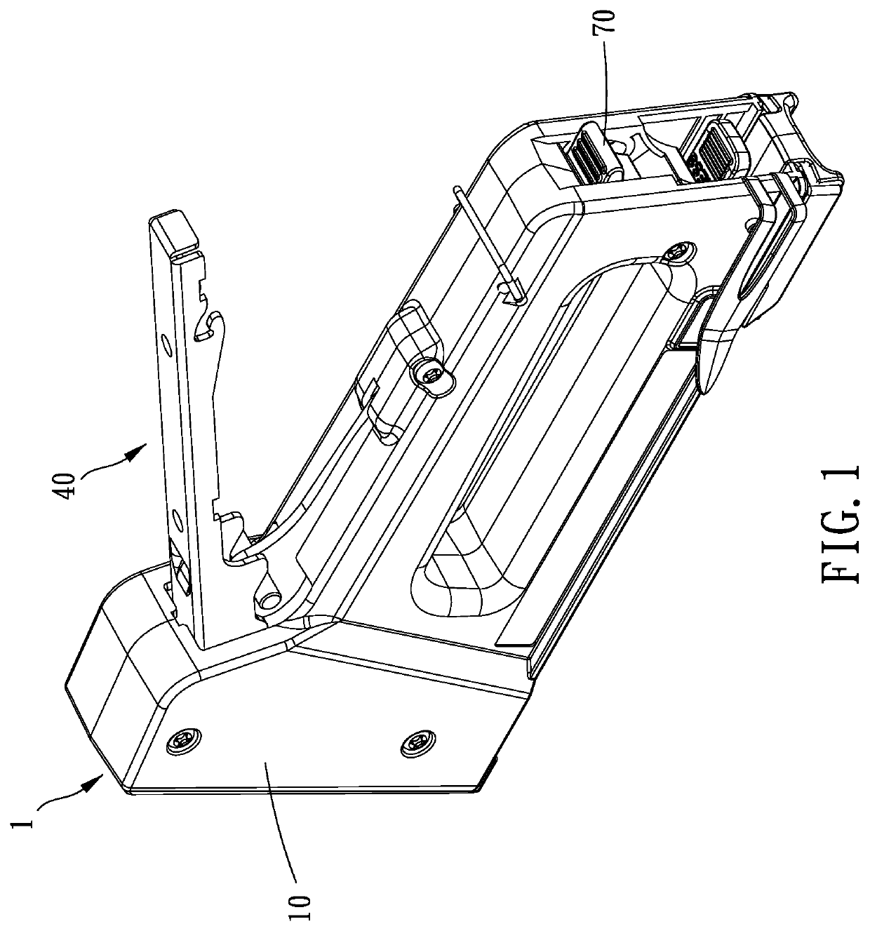
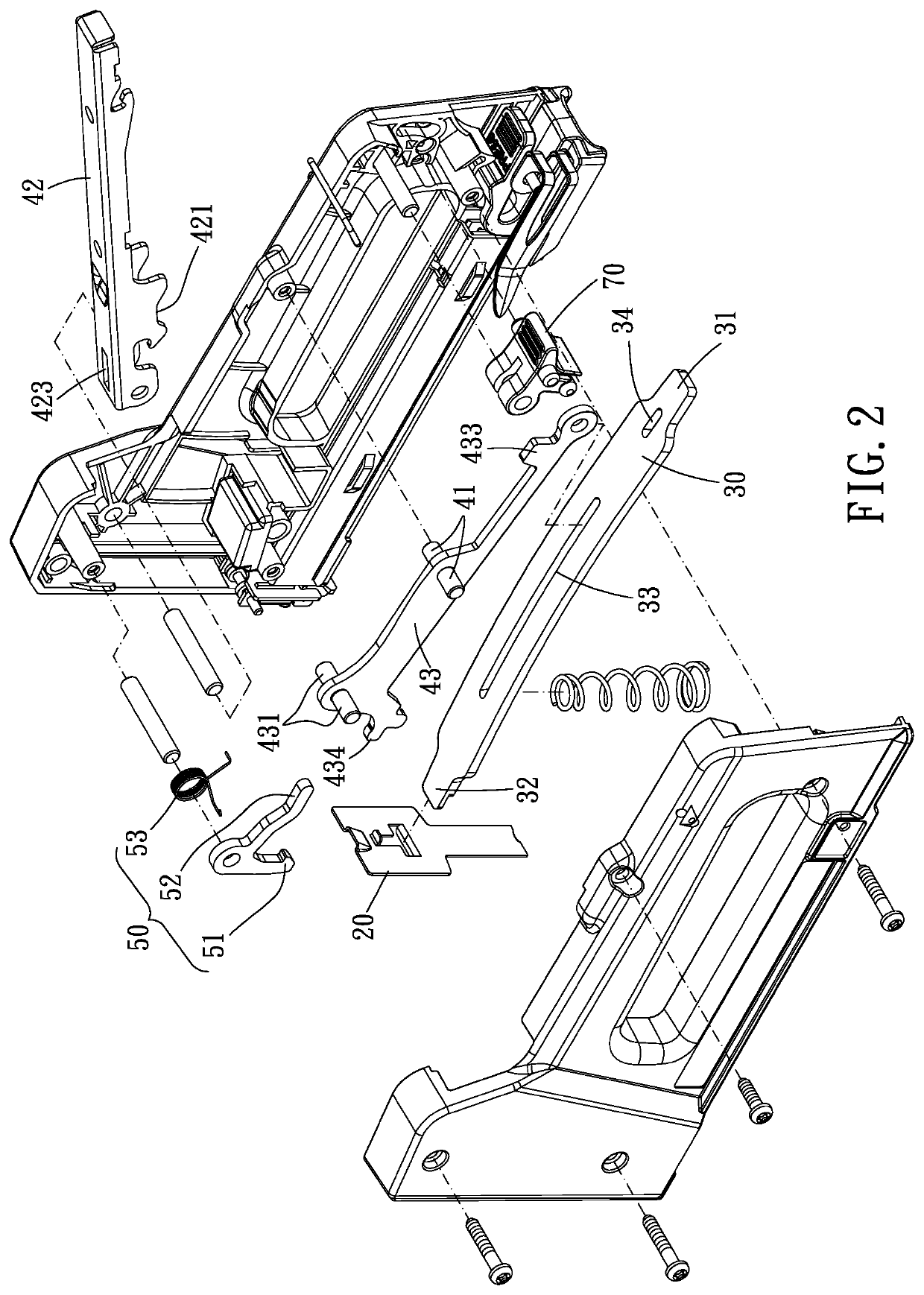
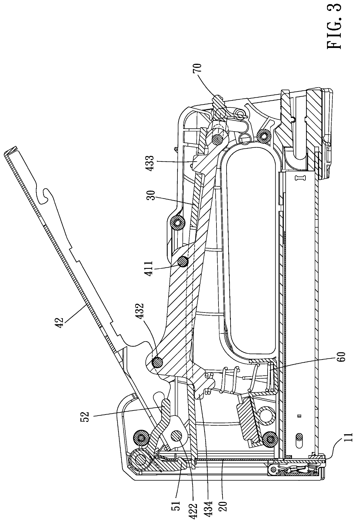
[0015]Please refer to FIGS. 1 to 5 for a preferred embodiment of the present invention. A labor-saving stapler 1 includes a housing 10, a striker 20, an energy-accumulating mechanism 30, an operable mechanism 40 and a limitation mechanism 50.

[0016]The housing 10 has a nail outlet 11. The striker 20 is disposed within the housing 10 and movable between a preset position distant from the nail outlet 11 and a nailing position near the nail outlet 11. The energy-accumulating mechanism 30 includes a connection portion 31 connected to the housing 10 and a connection end 32 cooperating with the striker 20, and the energy-accumulating mechanism 30 is deformable to be in an energy-accumulating state or a releasing state. The operable mechanism 40 is movab...


PUM


Abstract

A labor-saving stapler is provided, including: a housing, having a nail outlet; a striker, disposed within the housing and movable between a preset position away from the nail outlet and a nailing position near the nail outlet; an energy-accumulating mechanism, including a connection portion connected to the housing and a connection end cooperating with the striker; an operable mechanism, movably connected to the housing and having a depression portion abutable against the energy-accumulating mechanism; a limitation mechanism, connected to the housing, the striker being positionably restricted by the limitation mechanism; wherein when the striker is in a preset position and positionably restricted by the limitation mechanism, the energy-accumulating mechanism is depressible by the depression portion to be in a energy-accumulating state, and when the striker is free of restriction by the limitation mechanism, the energy-accumulating mechanism actuates the striker to move toward the nailing position.

Description

BACKGROUND OF THE INVENTION[0001]The present invention is a CIP of application Ser. No. 15 / 074,369, filed Mar. 18, 2016, the entire contents of which are hereby incorporated by reference.FIELD OF THE INVENTIONDescription of the Prior Art[0002]Usually, in a conventional stapler, as disclosed in TWI336286 and U.S. Pat. No. 6,789,719, a grip portion swings to actuate a connection rod in the stapler to swing so as to move a striker which slides straightly to a position to be struck. In the meanwhile, the striker is abutted against by a spring or an elastic sheet, when the striker moves toward the position to be struck, the elastic sheet is bent to accumulate energy; and when the connection rod swings to separate from the striker, the striker is bounded by the elastic member to move downward quickly to strike a nail.[0003]In actual use, this type of stapler has a more complex structure, and it is more labor-consuming to use the stapler. Firstly, the stapler releases the striker through t...

Claims


Application Information

Patent Timeline
Patent Type & Authority Patents(United States)
IPC IPC(8): B25C5/11B25C5/02B25C5/06
CPCB25C5/11B25C5/0285B25C5/06
Inventor WANG, JING-LI
Owner APEX MFG
Why Eureka
Try Eureka