
Electromagnetic drive type plunger pump

a technology of electric drive and plunger pump, which is applied in the direction of piston pump, positive displacement liquid engine, machine/engine, etc., can solve the problems of not being performed, the plunger b, 3/b> cannot be operated, etc., and achieve the effect of reducing noise, simple structure and compressing the volume of the plunger at a full-stroke position

Inactive Publication Date: 2006-08-22
MIKUNI CORP
View PDF12 Cites 15 Cited by
  • Summary
  • Abstract
  • Description
  • Claims
  • Application Information

AI Technical Summary

Benefits of technology

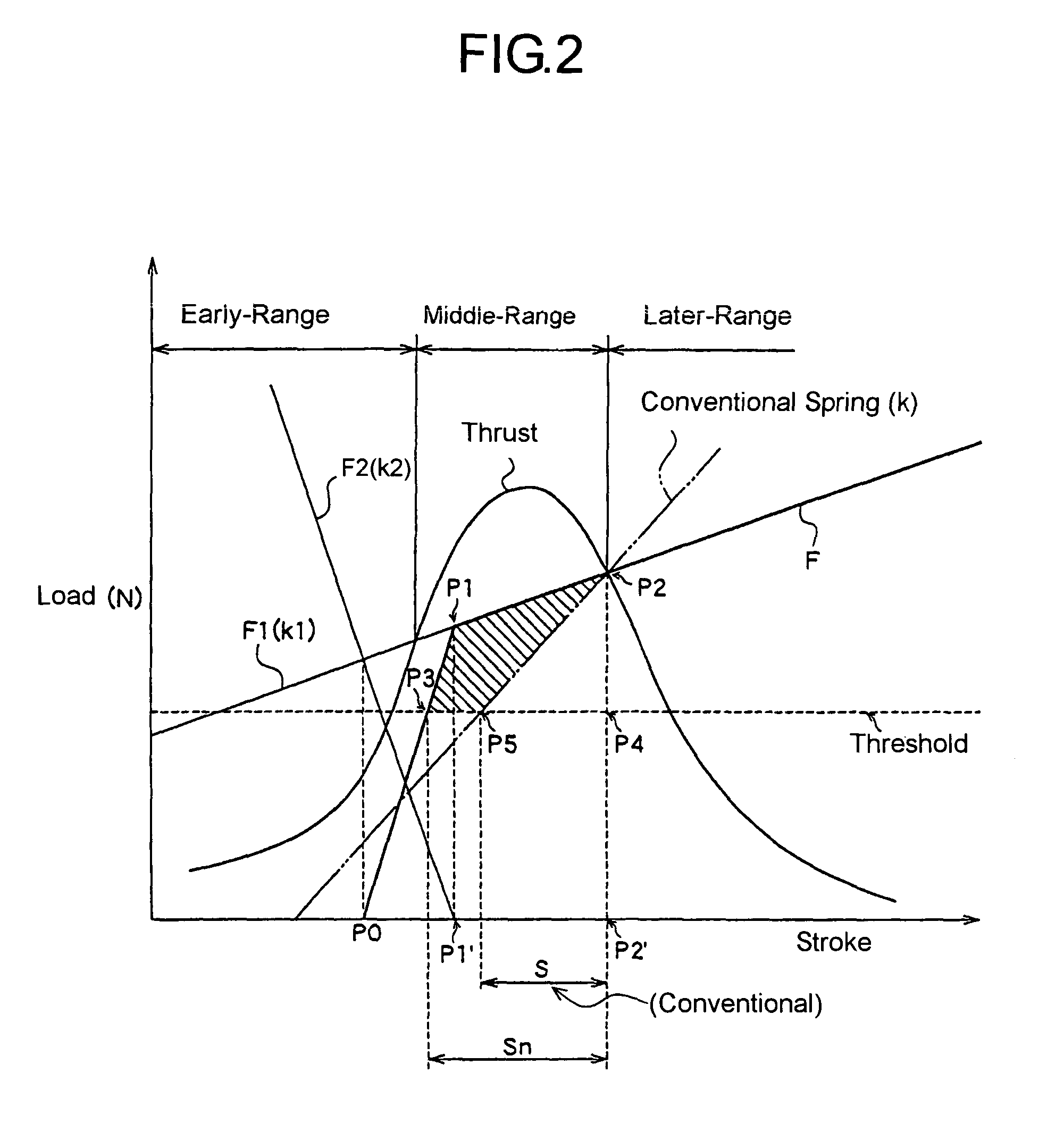
[0011]With this structure, in the early range with relatively small thrust of mountain-shaped thrust characteristic curve, the urging force (load) of the feeding spring, which is set larger than the thrust (the spring constant is relatively small), is reduced to be smaller than the thrust by the urging force (load) of the second spring which urges in a direction against the feeding spring. The refore, the thrust can move the plunger in this early range, and a moving stroke of the plunger is enlarged, namely, energy accumulated in the feeding spring is increased, due to spring characteristics of the feeding spring and the second spring. Hence, a high efficient discharging (feeding) characteristic is obtained and a discharging amount (feeding amount) of the fuel is increased.
[0019]With the above-mentioned structure, the second spring can be a coil spring with a section thereof being rectangle-shaped (angular shape). With this structure, because a setting length of the second spring can be shortened, a compressed volume of when the plunger is at a full-stroke position can be reduced, and a compression rate of the fuel to be fed is increased. In this manner, a self-absorption capability can be improved.

Problems solved by technology

Consequently, even if power is supplied during a sucking process, the plunger 3 cannot be operated and compression of the spring 2, namely accumulation of the energy, is not performed.
Accordingly, a discharging amount (feeding amount) cannot be increased, and an increase of power consumption or upsizing of the solenoid coil is needed to obtain a necessary discharging amount.

Method used


Image

  • Electromagnetic drive type plunger pump
  • Electromagnetic drive type plunger pump
  • Electromagnetic drive type plunger pump

Examples


Embodiment Construction

[0028]The embodiments of the present invention are explained in the following based on the attached drawings.

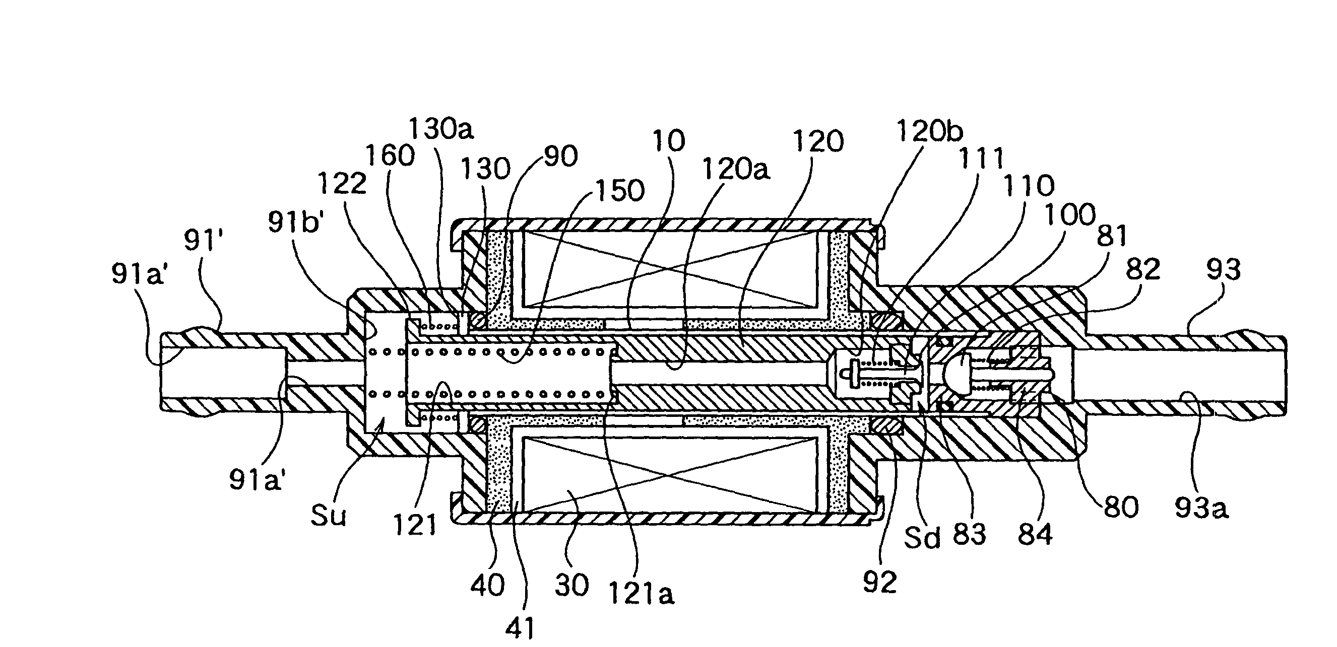
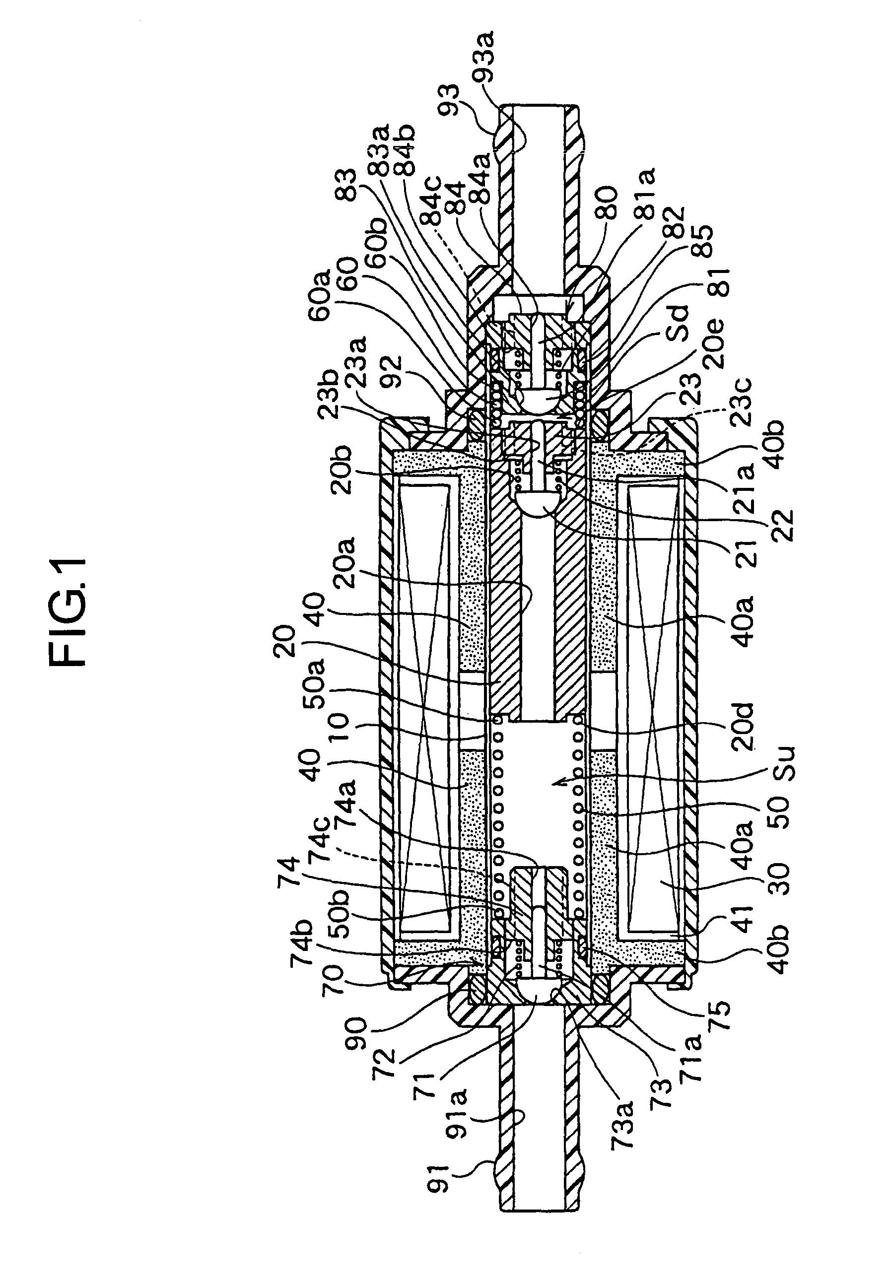
[0029]FIG. 1 is a sectional view showing an embodiment of an electromagnetically driven type plunger pump of the present invention. The electromagnetically driven type plunger pump of this embodiment feeds fuel for an engine and the like as a liquid. As shown in FIG. 1, the pump comprises a cylinder 10 as a cylindrical body whose shape is cylindrical, a plunger 20 disposed in a passage of the cylinder 10 and having intimate contact therewith and being free to reciprocate therein, a magnetic circuit including a solenoid coil 30 and a yoke 40 which generate electromagnetic force to exert thrust to the plunger 20, a feeding spring 50 which accumulates energy for feeding a liquid, and a second spring 60 which generates urging force in a direction against an urging force of the feeding spring 50, as a basic structure.

[0030]The plunger 20 is a movable member having a specific lengt...


PUM


Abstract

With structure comprising a cylinder, a magnetic circuit to exert a mountain-shaped thrust, and a feeding spring to exert an urging force to a plunger during a feeding process, fuel is sucked by movement of the plunger and energy is accumulated in the feeding spring during a powering state, the fuel is fed by movement of the plunger by the urging force of the feeding spring during a non-powering state, a spring constant of the feeding spring is set to generate an urging force larger than a thrust in an early range of the mountain-shaped thrust, and a second spring is disposed to exert an urging force in a direction against the urging force of the feeding spring to make the urging force smaller than the thrust, at least in the early range. In this manner, with an electromagnetically driven type plunger pump of a non-powering feeding type, an effective stroke is enlarged and a feeding amount is increased.

Description

[0001]This application is a National Stage application of PCT / JP01 / 09123, filed Oct. 17, 2001.TECHNICAL FIELD[0002]The present invention relates to an electromagnetically driven type plunger pump, which sucks and feeds a liquid such as engine fuel and the like, and especially relates to an electromagnetically driven type plunger pump of a non-powering feed type, which sucks a liquid by movement of a plunger and accumulates energy in a spring during a powering state, and feeds the liquid with this accumulated energy during a non-powering state.BACKGROUND ART[0003]A conventional electromagnetically driven type plunger pump of a non-powering feed type comprises, for example, a plunger which is disposed in a cylinder (a cylindrical body) and being free to reciprocate, a pair of springs which exert specific urging force to the plunger from both ends thereof while having consistent contact therewith, a solenoid coil which exerts thrust (electromagnetic force) to the plunger to suck a liqu...

Claims


Application Information

Patent Timeline
IPC IPC(8): F04B35/04F04B17/04
CPCF04B17/046F04B17/04
Inventor HASHIMOTO, SHOGOEHARA, RYOJITAKAHASHI, JUNICHIRO
Owner MIKUNI CORP
Learn More