
Method and apparatus for suppressing wind noise

a wind noise and apparatus technology, applied in the field of acoustics, can solve the problems of severe degrading of the quality of an acoustic signal, and inability to achieve high-speed wind noise suppression

Active Publication Date: 2004-08-26
MALIKIE INNOVATIONS LTD
View PDF98 Cites 251 Cited by
  • Summary
  • Abstract
  • Description
  • Claims
  • Application Information

AI Technical Summary

Benefits of technology

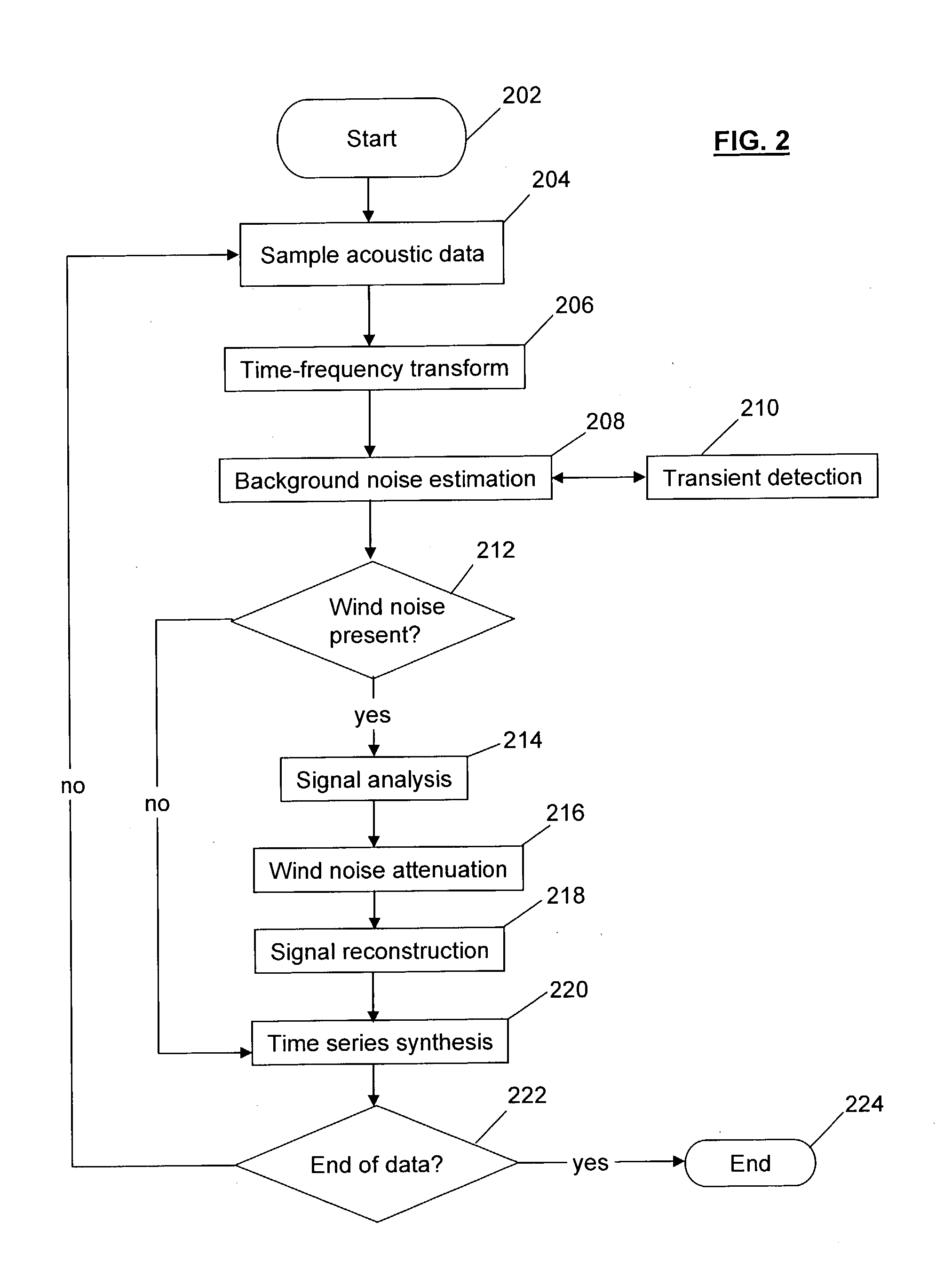
[0009] The preferred embodiment of the invention attenuates wind noise in acoustic data as follows. Sound input from a microphone is digitized into binary data. Then, a time-frequency transform (such as short-time Fourier transform) is applied to the data to produce a series of frequency spectra. After that, the frequency spectra are analyzed to detect the presence of wind noise and narrow-band signal, such as voice, music, or machinery. When wind noise is detected, it is selectively suppressed. Then, in places where the signal is masked by the wind noise, the signal is reconstructed by extrapolation to the times and frequencies. Finally, a time series that can be listened to is synthesized. In another embodiment of the invention, the system suppresses all low frequency wide-band noise after having performed a time-frequency transform, and then synthesizes the signal.
[0010] The invention has the following advantages: no special hardware is required apart from the computer that is performing the analysis. Data from a single microphone is necessary but it can also be applied when several microphones are available. The resulting time series is pleasant to listen to because the loud wind puffing noise has been replaced by near-constant low-level noise and signal.

Problems solved by technology

This puffing sound can severely degrade the quality of an acoustic signal.
Such a physical barrier is not always practical or feasible.
The physical barrier methods also fail at high wind speed.
These prior art inventions require the use of special hardware, severely limiting their applicability and increasing their cost.

Method used


Image

  • Method and apparatus for suppressing wind noise
  • Method and apparatus for suppressing wind noise
  • Method and apparatus for suppressing wind noise

Examples


Embodiment Construction

. It will be apparent, however, to one skilled in the art, that the present invention may be practiced without these specific details. In other instances, well known details have not been provided so as to not obscure the invention.

[0023] Overview of Operating Environment

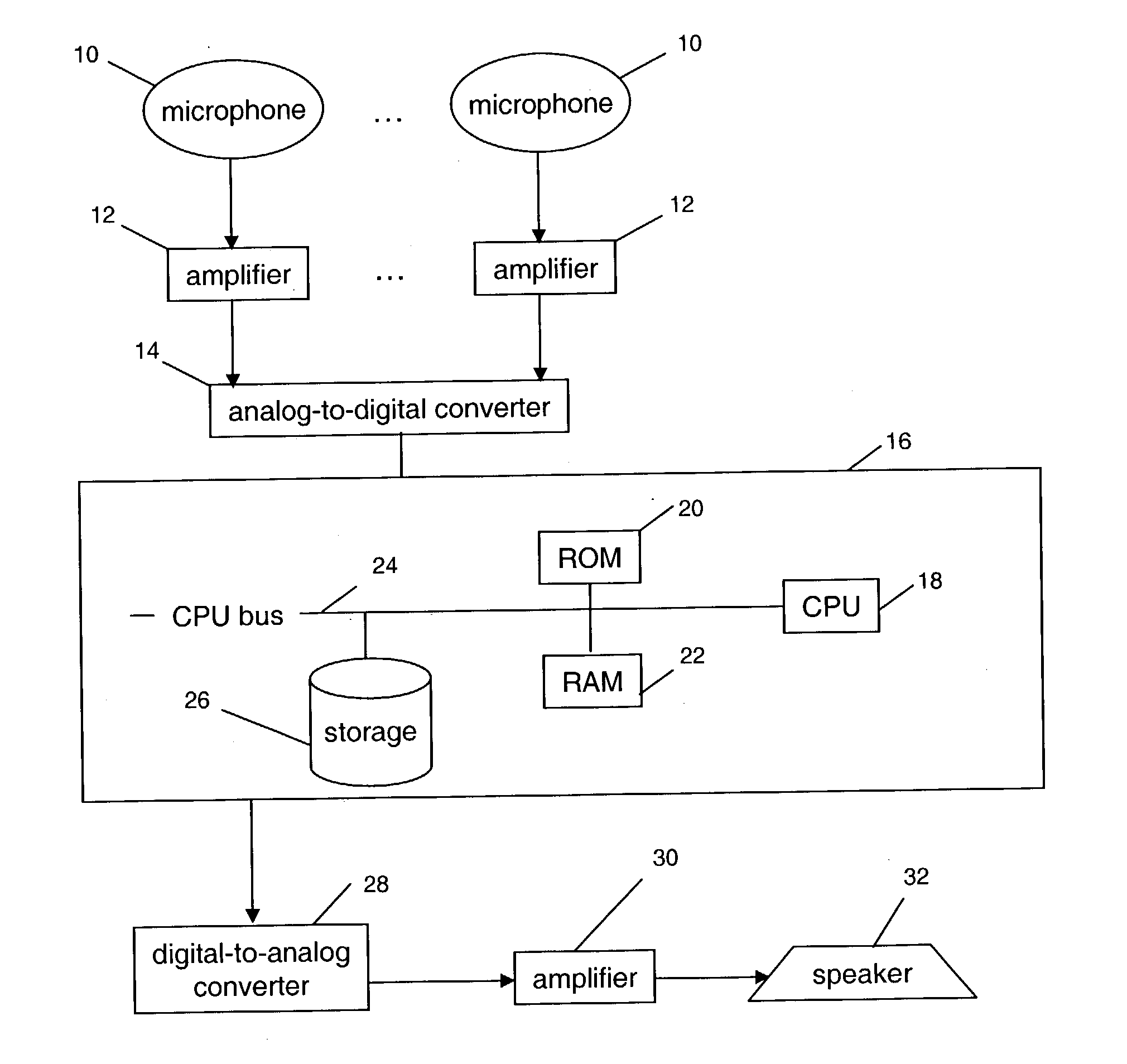
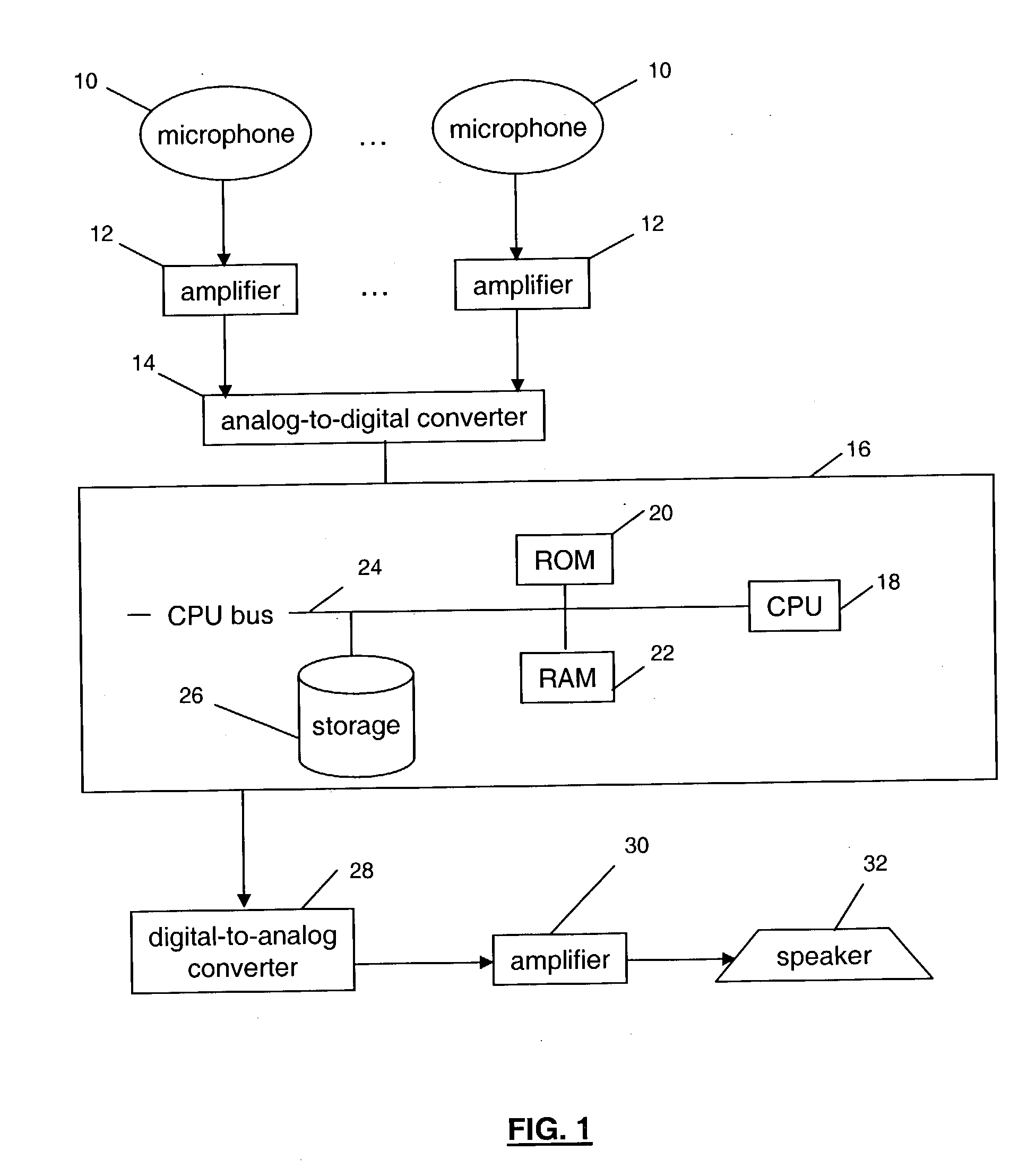
[0024] FIG. 1 shows a block diagram of a programmable processing system which may be used for implementing the wind noise attenuation system of the invention. An acoustic signal is received at a number of transducer microphones 10, of which there may be as few as a single one. The transducer microphones generate a corresponding electrical signal representation of the acoustic signal. The signals from the transducer microphones 10 are then preferably amplified by associated amplifiers 12 before being digitized by an analog-to-digital converter 14. The output of the analog-to-digital converter 14 is applied to a processing system 16, which applies the wind attenuation method of the invention. The processing system may...


PUM


Abstract

The invention includes a method, apparatus, and computer program to selectively suppress wind noise while preserving narrow-band signals in acoustic data. Sound from one or several microphones is digitized into binary data. A time-frequency transform is applied to the data to produce a series of spectra. The spectra are analyzed to detect the presence of wind noise and narrow band signals. Wind noise is selectively suppressed while preserving the narrow band signals. The narrow band signal is interpolated through the times and frequencies when it is masked by the wind noise. A time series is then synthesized from the signal spectral estimate that can be listened to. This invention overcomes prior art limitations that require more than one microphone and an independent measurement of wind speed. Its application results in good-quality speech from data severely degraded by wind noise.

Description

[0001] This application claims the benefit of U.S. Provisional Patent Application No. 60 / 449,511, filed Feb. 21, 2003.[0002] 1. Field of the Invention[0003] The present invention relates to the field of acoustics, and in particular to a method and apparatus for suppressing wind noise.[0004] 2. Description of Related Art[0005] When using a microphone in the presence of wind or strong airflow, or when the breath of the speaker hits a microphone directly, a distinct impulsive low-frequency puffing sound can be induced by wind pressure fluctuations at the microphone. This puffing sound can severely degrade the quality of an acoustic signal. Most solutions to this problem involve the use of a physical barrier to the wind, such as fairing, open cell foam, or a shell around the microphone. Such a physical barrier is not always practical or feasible. The physical barrier methods also fail at high wind speed. For this reason, prior art contains methods to electronically suppress wind noise.[...

Claims


Application Information

Patent Timeline
Patent Type & Authority Applications(United States)
IPC IPC(8): H04R3/00
CPCG10L21/0232G10L21/0208G10L21/0264G10L2021/02163H04R2410/07
Inventor HETHERINGTON, PHILLI, XUEMANZAKARAUSKAS, PIERRE
Owner MALIKIE INNOVATIONS LTD
Learn More