Liquid agent mist recovery device

US11110711B2Active Publication Date: 2021-09-07RISO KAGAKU CORP
11 Cites 0 Cited by

Patent Information

Authority / Receiving Office
US · United States
Patent Type
Patents(United States)
Current Assignee / Owner
Publication Date
2021-09-07

Smart Images

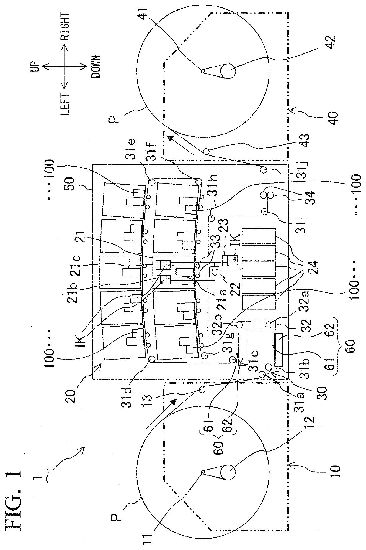
  • Figure 1
    Figure 1
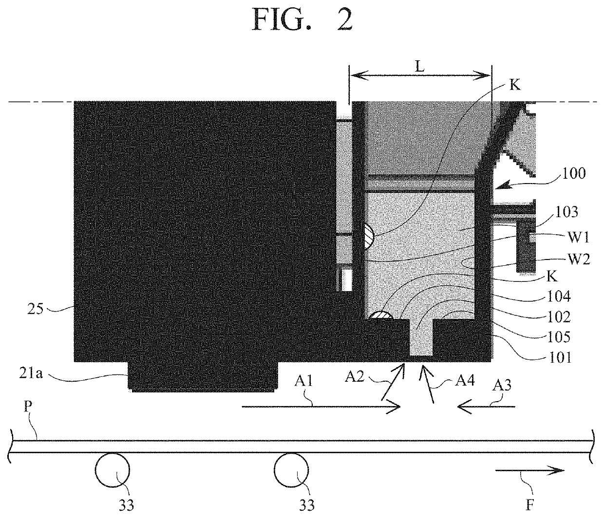
  • Figure 2
    Figure 2
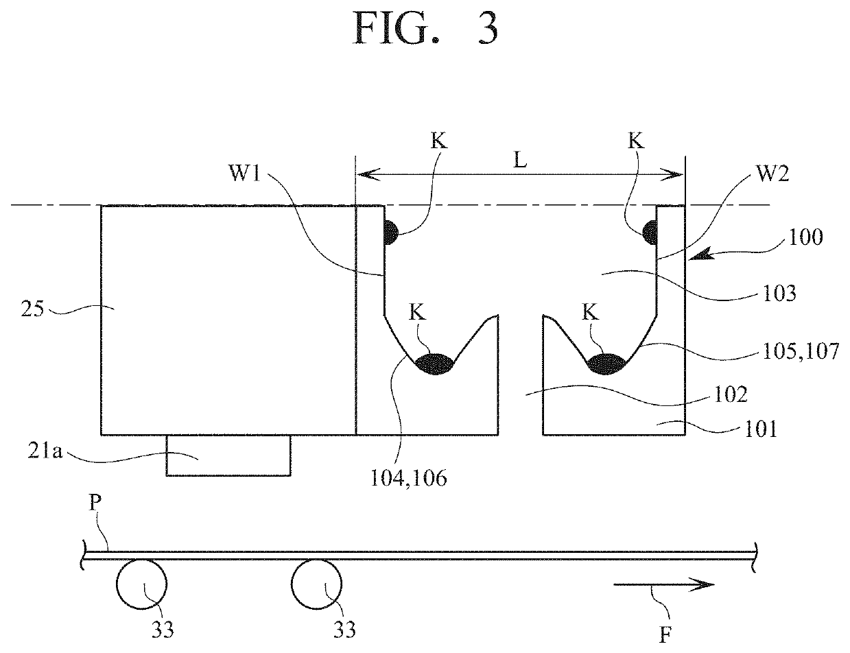
  • Figure 3
    Figure 3
Patent Text Reader

Abstract

A liquid agent mist recovery device for a liquid agent application device prevents dripping of a droplet formed from a sucked liquid agent mist onto a sheet. The ink mist recovery device installed downstream of an inkjet head includes a recovery casing with an opening for introducing the mist. The opening is communicated with a recovery hole connected to a suction fun, and positioned apart from an upstream wall surface by a distance corresponding to receiving portions for receiving a droplet trickling from the wall surface, and apart from a downstream wall surface so that air introduced from downstream obstructs the flow of the upstream liquid agent mist for guiding into the recovery hole. The liquid agent mist from upstream is securely introduced and recovered. The liquid agent mist trickling from the wall surface of the recovery hole is received by the receiving portion rather than dripping onto the sheet.
Need to check novelty before this filing date? Find Prior Art

Description

BACKGROUND OF THE INVENTION

[0001] The present invention relates to a liquid agent mist recovery device that is installed in a liquid agent application device for discharging the liquid agent to a sheet being carried, and is configured to allow a suction unit to introduce the liquid agent mist generated during discharge of the liquid agent into a duct for recovery. Particularly, the present invention relates to the liquid agent mist recovery device capable of preventing a droplet formed from the introduced liquid agent mist from dripping onto the sheet.

[0002] Japanese Unexamined Patent Application Publication No. 2015-134496 discloses the ink mist recovery device intended to suppress adhesion of the ink mist to the inner surface of the suction flow path. As FIG. 2 of the disclosure shows, the ink mist recovery section 3 is disposed apart from the recording head 1 downstream at a predetermined gap in a carrier direction Y of the recording medium 5. The ink mist recovery section 3 sucks ...

Examples

Embodiment Construction

[0011]An embodiment of the present invention will be described referring to FIGS. 1 to 4. This embodiment relates to an inkjet printer 1 provided with an ink mist recovery device 100. The ink mist recovery device 100 is one specific example of the liquid agent mist recovery device according to the present invention. The inkjet printer 1 is a preferred example to which the ink mist recovery device is applied.

[0012]FIG. 1 is an overall structure view of the inkjet printer 1 according to the embodiment in a front view. Descriptions indicating directions such as an up-down direction, a left-right direction (those two directions are indicated by arrows in FIG. 1), and a front-rear direction (direction perpendicular to the drawing) are mere terms for convenience of explanation. Specifically, the up-down direction refers to the vertical direction. The left-right and the front-rear directions refer to those orthogonal to each other in the horizontal plane.

[0013]As FIG. 1 shows, the inkjet p...