
Coil electrode for a fluorescent lamp

Inactive Publication Date: 2002-03-28
PATENT TREUHAND GESELLSCHAFT FUR ELECTRIC GLUEHLAMPEN MBH
View PDF6 Cites 1 Cited by
  • Summary
  • Abstract
  • Description
  • Claims
  • Application Information

AI Technical Summary

Benefits of technology

[0006] For a coil electrode having the features of the precharacterizing clause of claim 1, this object is achieved by a connection path which is formed between the two connection regions of the two coil ends being located outside of the coil body. This is because, in this particular case, the coil body can be immersed in an emitter paste without the connection regions and hence the power supply sections at the same time coming into contact with the emitter. The immersion process allows the coil body to be wetted with a relatively large amount of emitter paste, which essentially governs the life of a fluorescent lamp.
[0007] A first advantageous development of the invention provides for the coil body to have a coil axis running in a straight line. This form of coil axis, in particular, ensures uniform charge carrier emission from the coil body.
[0008] In a further advantageous refinement of the invention, the coil body has at least one end section which is adjacent to one coil end and has an end section axis, with the adjacent coil end having at least one coil end section between the end section and the connection region, and with the at least one coil end section having a profile which has a direction component that is not equal to zero at every point and is arranged at right angles to the end section axis. This refinement of the invention is particularly advantageous when the at least one coil end section occupies the entire region of the coil end between the end section and the connection region, and when the coil body has a coil axis running in a straight line, or which is only slightly bent. This is because the emitter, which is located on the at least one coil end section, is then passed in the direction of the coil body, and it is possible to avoid droplets being formed on the coil end.
[0013] In one particularly advantageous development, the coil electrode is connected to the two power supply sections without any mechanical stress, either with the low-pressure discharge lamp switched on or with the low-pressure discharge lamp switched off. Such an attachment process without any mechanical stress in one of these states avoids any forces acting on the coil electrode in this state which would reduce its life.

Problems solved by technology

Problems which are caused by the emitter coming into contact with the power supply sections frequently occur during the process of pasting the coil electrode.
In this case, it is impossible to carry out the forming process correctly, and the coil electrode together with the connected power supply sections must be scrapped.
Particularly in the case of a low-pressure discharge lamp with a small internal bulb diameter and a correspondingly small coil body, it is virtually impossible to prevent the emitter coming into contact with the power supply sections.
A further disadvantage of the already known coil electrode is that droplets are frequently formed on the coil ends immediately after the pasting process and prevent the pasting process and the subsequent forming process from being carried out smoothly.

Method used


Image

  • Coil electrode for a fluorescent lamp
  • Coil electrode for a fluorescent lamp
  • Coil electrode for a fluorescent lamp

Examples


first embodiment

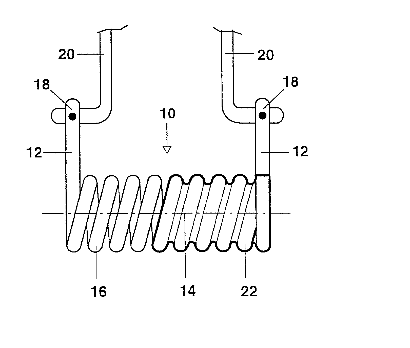
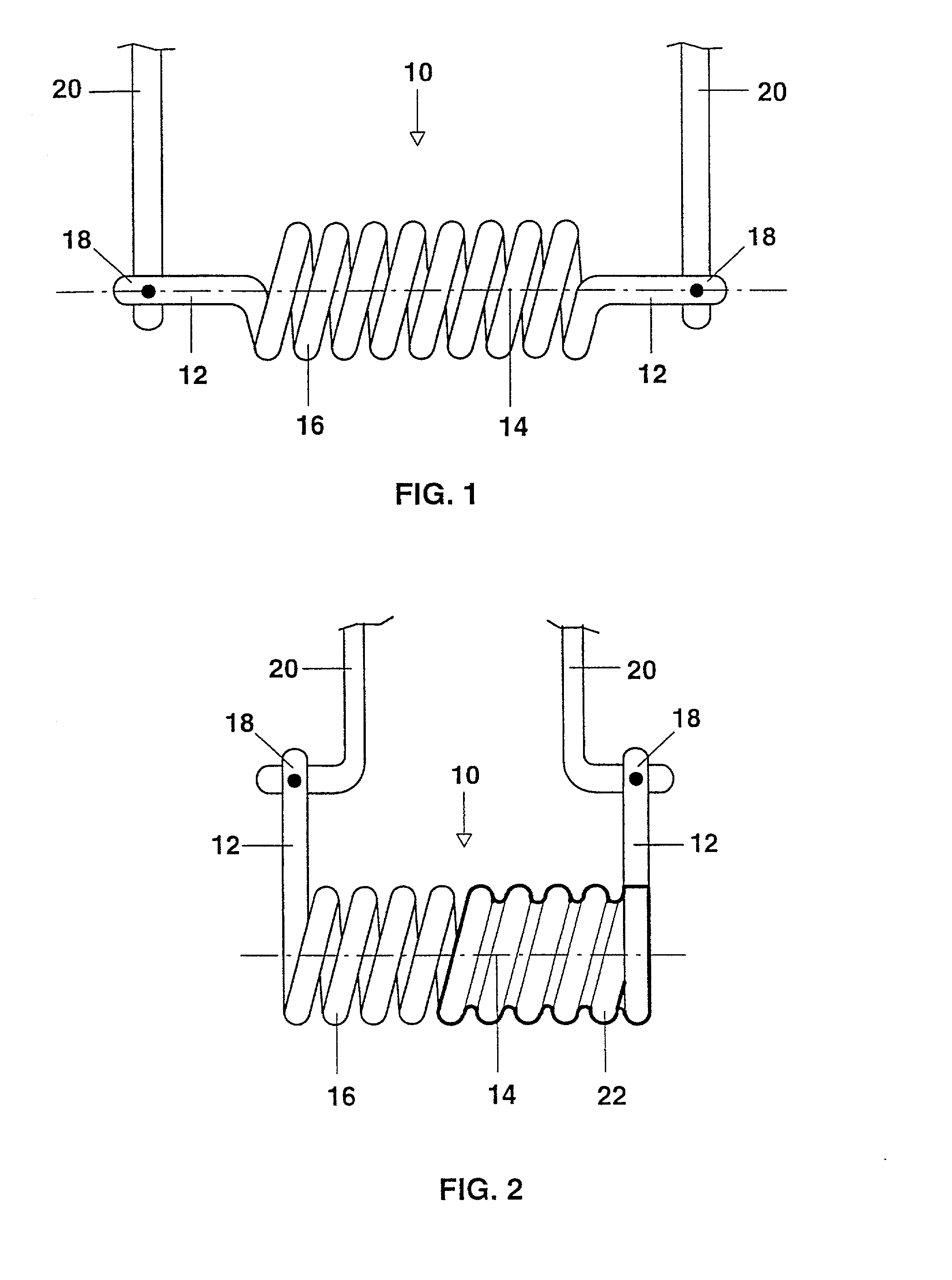
[0016] FIG. 2 shows a schematic illustration of a coil electrode according to the invention,

second embodiment

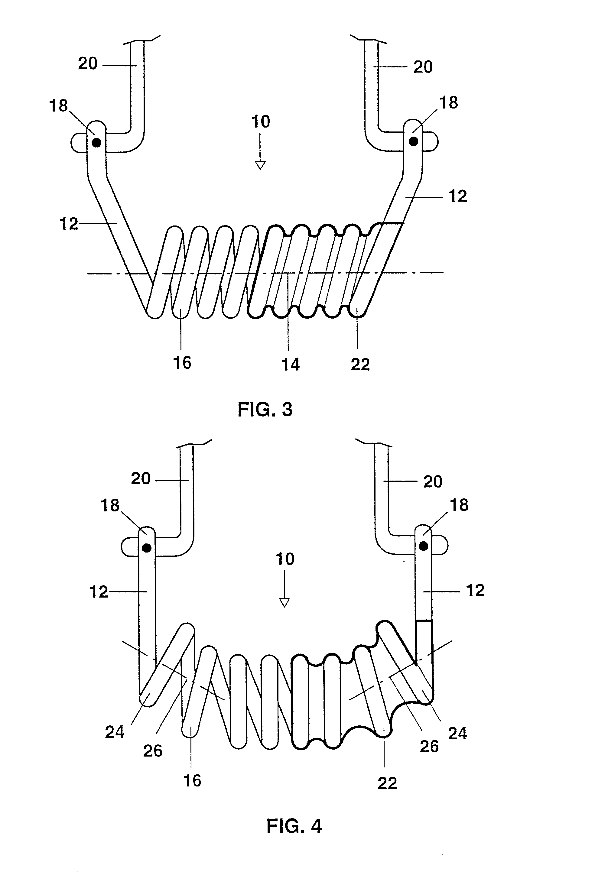
[0017] FIG. 3 shows a schematic illustration of a coil electrode according to the invention; and

third embodiment

[0018] FIG. 4 shows a schematic illustration of a coil electrode according to the invention.

[0019] FIG. 2 is a schematic illustration of a first embodiment of a coil electrode 10 according to the invention, which has two coil ends 12 and a coil body 16 with a coil axis 14 running in a straight line. The coil ends 12 are connected at connection regions 18 by welding or clamping to power supply sections 20. In order to wet the coil body 16 with emitter 22, the entire coil body 16 is immersed in an emitter paste 22, with the emitter 22, as shown in FIG. 2, adhering to the coil body. The connection regions 18, and hence the power supply sections 20 as well, in contrast remain free of emitter 22, so that the shaping process can be carried out correctly. If any emitter 22 is likewise located on the coil ends 12, the force of gravity moves this in the direction of the coil body 16. This prevents droplets from being formed on the coil ends 12. The coil electrode 10 is connected to the power...


PUM


Abstract

A coil electrode for a low-pressure discharge lamp includes a coil body and two coil ends that have connection regions at which they are connected to respective power supply sections. The connection path between the two connection regions is located outside the coil body.

Description

[0001] The invention is based on a coil electrode for a low-pressure discharge lamp, in particular a fluorescent lamp, as claimed in the precharacterizing clause of claim 1. This is, in particular, a coil electrode which has a coil body and two coil ends. In this case, the two coil ends each have a connection region, at which they can be conductively connected to a respective power supply section.PRIOR ART[0002] A coil electrode, which is explained in more detail with reference to FIG. 1 in the following text, is already known for use in a fluorescent lamp. The coil electrode 10 illustrated in FIG. 1 has coil ends 12 which run along the coil axis 14 of the coil body 16. Within a fluorescent lamp, the coil ends 12 are connected at their connection regions 18 to power supply sections 20 of the fluorescent lamp, by means of welding or clamping. In contrast to the illustration in FIG. 1, coil electrodes are also known whose coil ends run parallel to the coil axis of the coil body.[0003]...

Claims


Application Information

Patent Timeline
IPC IPC(8): H01J61/067
CPCH01J61/0672
Inventor WEINHARDT, EROLF
Owner PATENT TREUHAND GESELLSCHAFT FUR ELECTRIC GLUEHLAMPEN MBH
Learn More