Charging member and method for manufacturing the same

a charging member and charging technology, applied in the field of charging members, can solve the problems of difficult uniform roughening of difficult to form the surface layer with a rough surface, and difficult to uniformly roughen the surface of the surface layer, so as to reduce the thickness of the surface layer and improve the charging performance of the charging member

Active Publication Date: 2016-06-21
CANON KK
View PDF37 Cites 13 Cited by
  • Summary
  • Abstract
  • Description
  • Claims
  • Application Information

AI Technical Summary

Benefits of technology

[0026]According to the present invention, the number of points in contact with a photosensitive member is limited to thereby reduce a contact area with the photosensitive member. Owing to this, adhesion of a toner and external additives is suppressed even if it is used for a long time, enabling to provide a surface rarely contaminated with dirt. As a result, a charging member capable of maintaining uniform charge for a long time can be obtained.

Problems solved by technology

According to the inventors' trial, it was difficult to form the surface layer having a rough surface.
Particularly, it was difficult to disperse coarse particles stably in a coating liquid for forming a surface layer.
In consequence, it was difficult to uniformly roughen the surface of the surface layer.

Method used


Image

  • Charging member and method for manufacturing the same
  • Charging member and method for manufacturing the same
  • Charging member and method for manufacturing the same

Examples


example 1

Preparation of Charging Rollers 1-1 to 1-3

[0177]

[0178]To condensate 1, a solvent mixture of ethanol:2-butanol=1:1 (mass ratio) was added to adjust a solid substance concentration to 0.7%, 6.6% and 13.1%. These were designated as coating materials No. 1-1, 1-2 and 1-3.

[0179]

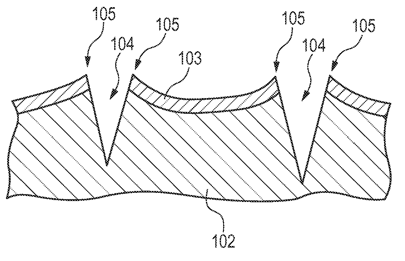
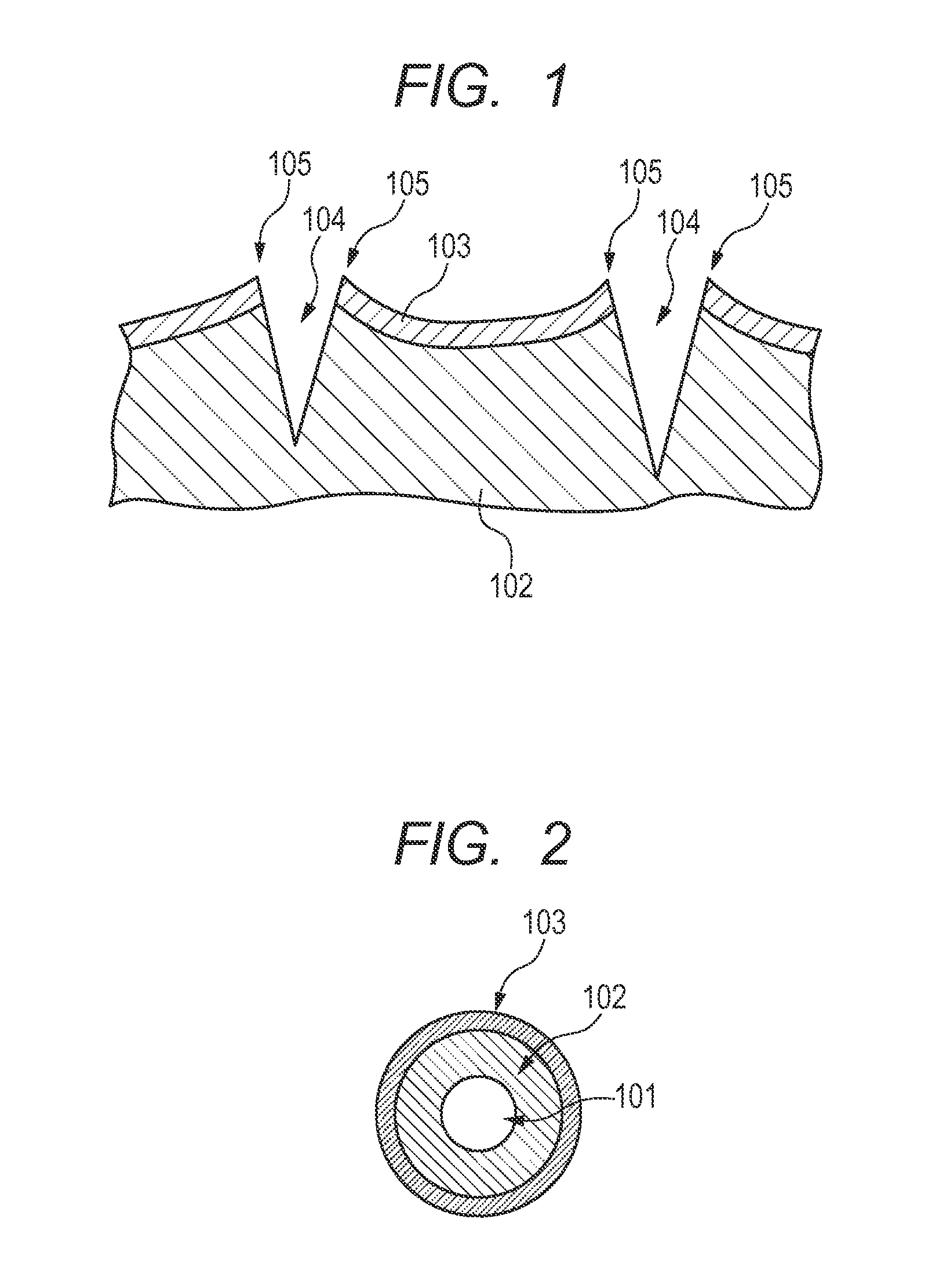
[0180]Three conductive elastic rollers 1 were prepared in the above [1]. To the outer peripheries of the conductive elastic layers of the conductive elastic rollers 1, coating materials No. 1-1 to 1-3 were applied, respectively, by ring coating (ejection amount: 0.120 ml / s, speed of a ring portion: 85 mm / s, total ejection amount: 0.130 ml). To the coating films of respective coating materials formed on the peripheral surfaces of the conductive elastic layers, UV ray having a wavelength of 254 nm was applied such that the cumulative light amount reached 9000 mJ / cm2. In this manner, condensate 1 of the coating material was crosslinked to form a surface layer. Note that irradiation of UV ray was performed by use of a...

examples 2 to 14

Preparation of Coating Materials 2-1 to 2-3, 3-1 to 3-3 for Forming a Surface Layer

[0197]Coating materials 2-1 to 2-3, 3-1 to 3-3 for forming a surface layer were prepared in the same manner as in coating materials 2-1 to 1-3 except that condensate 2 was used.

[0198]

[0199]To condensate 4, a solvent mixture of ethanol:2-butanol=1:1 (mass ratio) was added to control a solid substance concentration to be 0.3%, 6.6% and, 19.7%. These were designated as coating material Nos. 4-1, 4-2 and 4-3.

[0200]

[0201]To condensate 5, a solvent mixture of ethanol:2-butanol=1:1 (mass ratio) was added to control a solid substance concentration to be 0.3% and 19.7%. These were designated as coating material Nos. 5-1 and 5-2.

[0202]

[0203]To condensate 6, a solvent mixture of ethanol:2-butanol=1:1 (mass ratio) was added to control a solid substance concentration to be 0.3%, 6.6% and 19.7%. These were designated as coating material Nos. 6-1, 6-2 and 6-3.

[0204]

[0205]To each of condensates 7 to 14, a solvent mix...

example 15

Preparation of Coating Material 15 for Forming a Surface Layer

[0208]To condensate 15, a solvent mixture of ethanol:2-butanol=1:1 (mass ratio) was added to control a solid substance concentration to be 13.1%. This was designated as coating material No. 15.

[0209]

[0210]Charging rollers 15-1 to 15-6 were prepared in the same manner as in charging roller 1 except that coating material No. 15 was used and conductive rollers 2 to 7 were used in place of the conductive elastic roller 1, and subjected to evaluations (3) to (8).


PUM

PropertyMeasurementUnit
thicknessaaaaaaaaaa
thicknessaaaaaaaaaa
thicknessaaaaaaaaaa

Abstract

Provided is a charging member having a rough surface, thereby suppressing adhesion of dirt on the surface. A charging member having a supporting member, an elastic layer and a surface layer, in which the surface layer contains a polymer compound, which has a Si—O-M bond and at least one structural unit selected from structural units represented by the following general formula (1) and the following general formula (2), and has a structural unit represented by the following general formula (3); the charging member has cracks developing from the surface thereof and reaching the elastic layer; and the cracks each have convexly raised edges, by which the surface thereof is roughened.MO4 / 2  General formula (1)

Description

CROSS-REFERENCE TO RELATED APPLICATIONS[0001]This application is a continuation of International Application No. PCT / JP2011 / 072492, filed Sep. 22, 2011, which claims the benefit of Japanese Patent Application No. 2010-215811, filed Sep. 27, 2010.BACKGROUND OF THE INVENTION[0002]1. Field of the Invention[0003]The present invention relates to a charging member used in electrophotographic apparatuses and a method for manufacturing the same.[0004]2. Description of the Related Art[0005]In an electrophotographic apparatus, electrographic members are used, and examples of the electrophotographic member includes a charging member for charging an outer surface of a photosensitive member by being into contact with the outer surface, a developing member for developing an electrostatic latent image formed on the outer surface of the photosensitive member to form a toner image and a cleaning member for removing toner attached to the photosensitive member.[0006]As the charging member used herein,...

Claims


Application Information

Patent Timeline
Patent Type & Authority Patents(United States)
IPC IPC(8): B32B3/00G03G15/02
CPCG03G15/0233Y10T428/24479C08G77/56C08G77/58C09D183/14G03G15/0258
Inventor KURODA, NORIAKINAGAMINE, NORIKOTOMOMIZU, YUYA
Owner CANON KK
Why Eureka
Try Eureka