Automobile molding and fastener therefor

a technology for automobiles and fasteners, which is applied in the direction of snap fasteners, buckles, transportation and packaging, etc., can solve the problems of inability to recycle molding, inability to easily separate fasteners, and complicated recycling of automobile molding, so as to reduce the contact area of the base plate, reduce the contact resistance, and smooth the effect of operation

Inactive Publication Date: 2007-01-23
FALTEC CO LTD
View PDF20 Cites 74 Cited by
  • Summary
  • Abstract
  • Description
  • Claims
  • Application Information

AI Technical Summary

Benefits of technology

[0007]The present invention was conceived in consideration of the above-described circumstances and has as its objective the provision of an automobile molding and a fastener therefore, which enables a confident engagement to be maintained between the molding and the fastener when they are assembled together, and in which the fastener can be easily separated from the molding main body without causing damage to the parts due to cutting, etc., so that, following separation, both parts can be recycled.
[0041]In the present invention, protruding portions that are provided projecting out from the pair of elastic pieces provided on opposite sides of the base plate of the fastener engage from inside the housing space with engage-and-stop portions that are formed to the lateral walls of the fastener holder that are adjacent to the opening of the fastener holder. As a result, the fastener is fixed in place by the fastener holder. If the engagement between the protruding portions of the elastic pieces and the engage-and-stop portions of the fastener holder is released by manipulating the elastic pieces, the fastener can be removed from the fastener holder, and the fastener separated from the molding main body. As a result, the molding main body and the fastener can be separated without being damaged by cutting, etc. Therefore, for example, the fastener can be reused or recycled following separation.
[0042]The “engage-and-stop portion” referred to here is, for example, an engaging hole 37 formed passing through lateral walls 27 which are adjacent to the opening 26, as shown in FIG. 6(b), or an engaging concavity 37a which is cut into the housing space 29 side of lateral walls 27 which are adjacent to opening 26, as shown in FIG. 6(c). By engaging the protruding portions provided on the elastic pieces, it is possible to prevent the base plate from being pulled out of the housing space, and to enable stable housing of the base plate in the housing space.
[0043]In order to enable separation of the molding main body and the fastener by extracting the fastener which is fixed in place to the molding main body, it is not only necessary to be able to release the engagement between the protruding portions of the elastic pieces and the fastener holder's engage-and-stop portions, but also to smoothly carry out the operation of extracting the fastener from the fastener holder once the engagement is released. On this note, it is effective to reduce the contact resistance with the fastener mounting seat by forming the contact sites between the fastener and the fastener holder's fastener mounting seat so that they are in the form of protrusions extending from the base plate, or protrusions extending from the base end of the cover that is formed to the engaging portion of the fastener, for example, and, further, by forming the protrusions of the base plate and the base end of the cover to be in a form of a ridge that extends along the direction of insertion of the fastener into the fastener holder (more specifically, in the direction of insertion of the base plate into the housing space). By providing a design that ensures clearance between the molding main body and the base plate that is housed in the fastener holder's housing space, it is possible to confidently reduce the base plate's contact area with the molding main body and the fastener holder. As a result, the operation to remove the fastener from the fastener holder can be carried out smoothly.
[0044]It is also possible to use a fastener which has been separated from a molding main body in a fastener holder of a different design than that to which it had previously been affixed. By designing the fastener holder so that it can enable insertion and anchoring of a fastener in various types of molding main bodies, a single fastener can be utilized with molding main bodies of various types and designs. As a result, costs can be reduced.
[0045]In the present invention, the engagement between the protruding portions on the elastic pieces and the fastener holder's engage-and-stop portions is released by manipulating the elastic pieces of the fastener which has been fixed in place by the insertion of the base plate into the housing space of the fastener holder. As a result, it becomes possible to withdraw the fastener from the fastener holder and to separate the molding main body and the fastener without causing any damage from cutting or the like. Thus, for example, the separated molding main body and fastener can be reused or recycled, resulting in less waste and lower costs from reutilizing parts.

Problems solved by technology

However, recycling of automobile molding has been complicated by the fact that the typical design is one in which the fastener cannot be easily separated from the molding main body.
As a result, recycling of the molding is not possible.
Moreover, removal of fastener holder 6 and fastener 8 using a blade is dangerous and is not efficient due to the time required for this operation.
Thus, the number of cutting sites becomes numerous and efficiency is poor.

Method used


Image

  • Automobile molding and fastener therefor
  • Automobile molding and fastener therefor
  • Automobile molding and fastener therefor

Examples


Embodiment Construction

[0059]A first embodiment of the present invention will now be explained with reference to the accompanying figures.

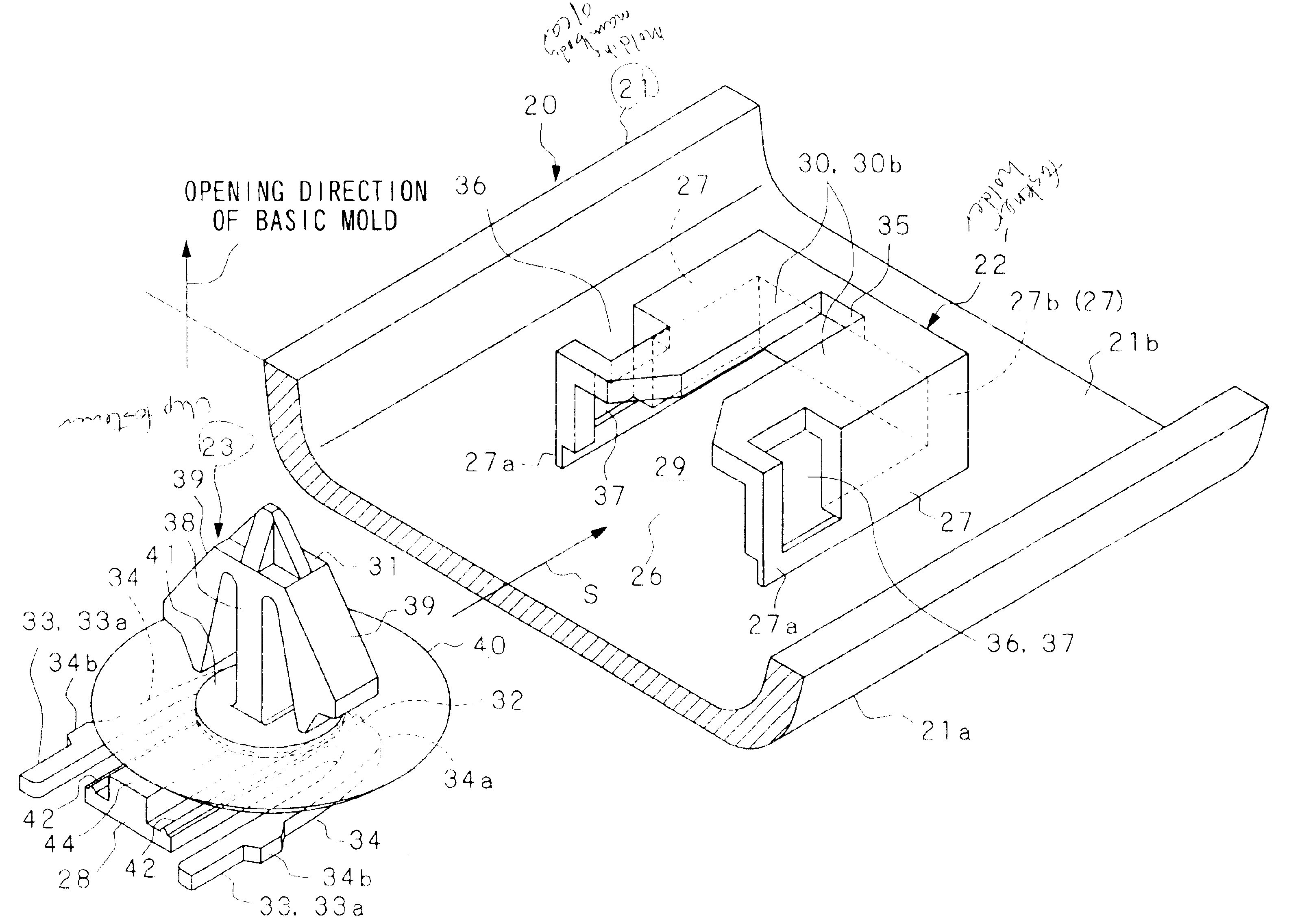
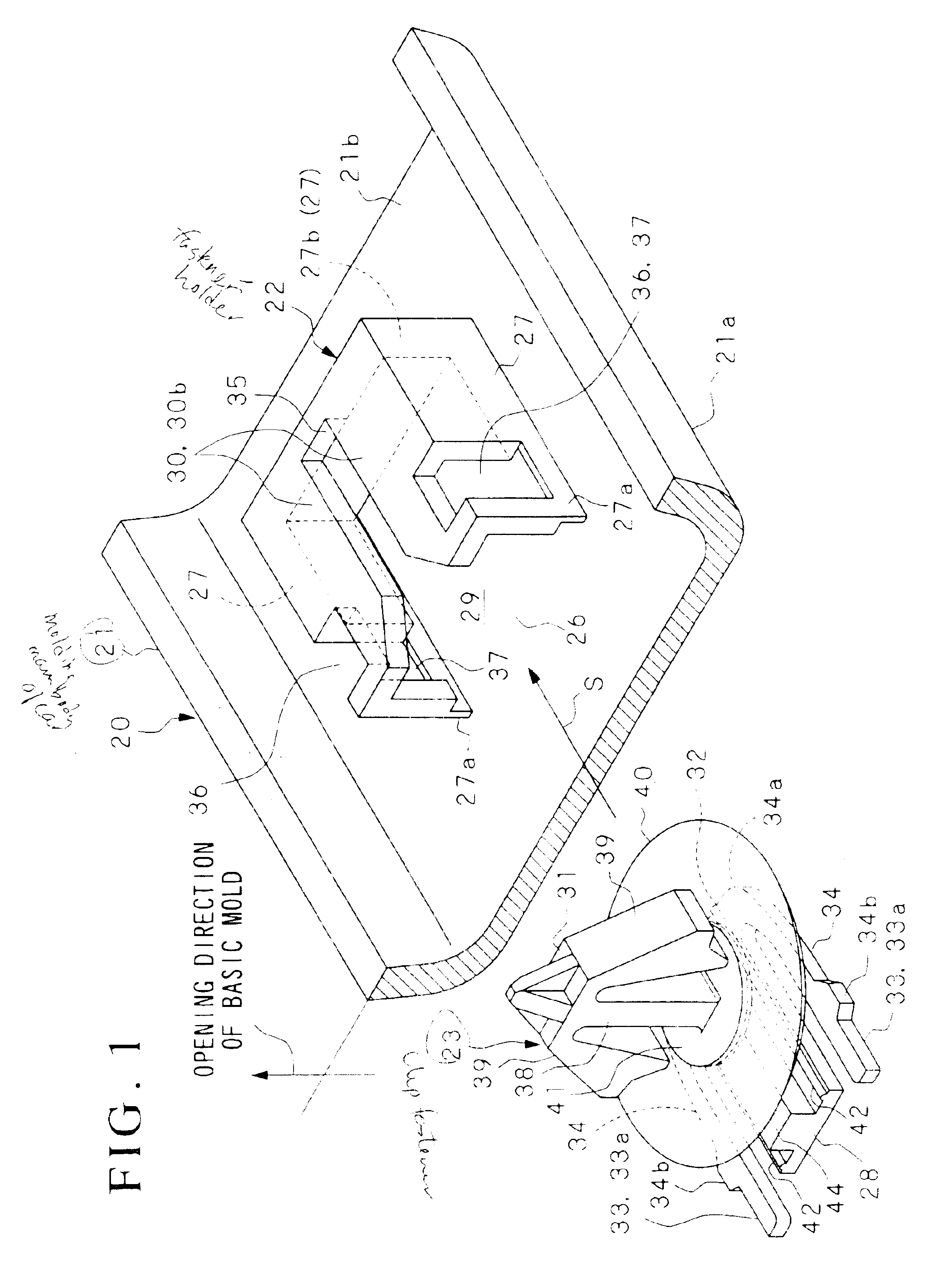
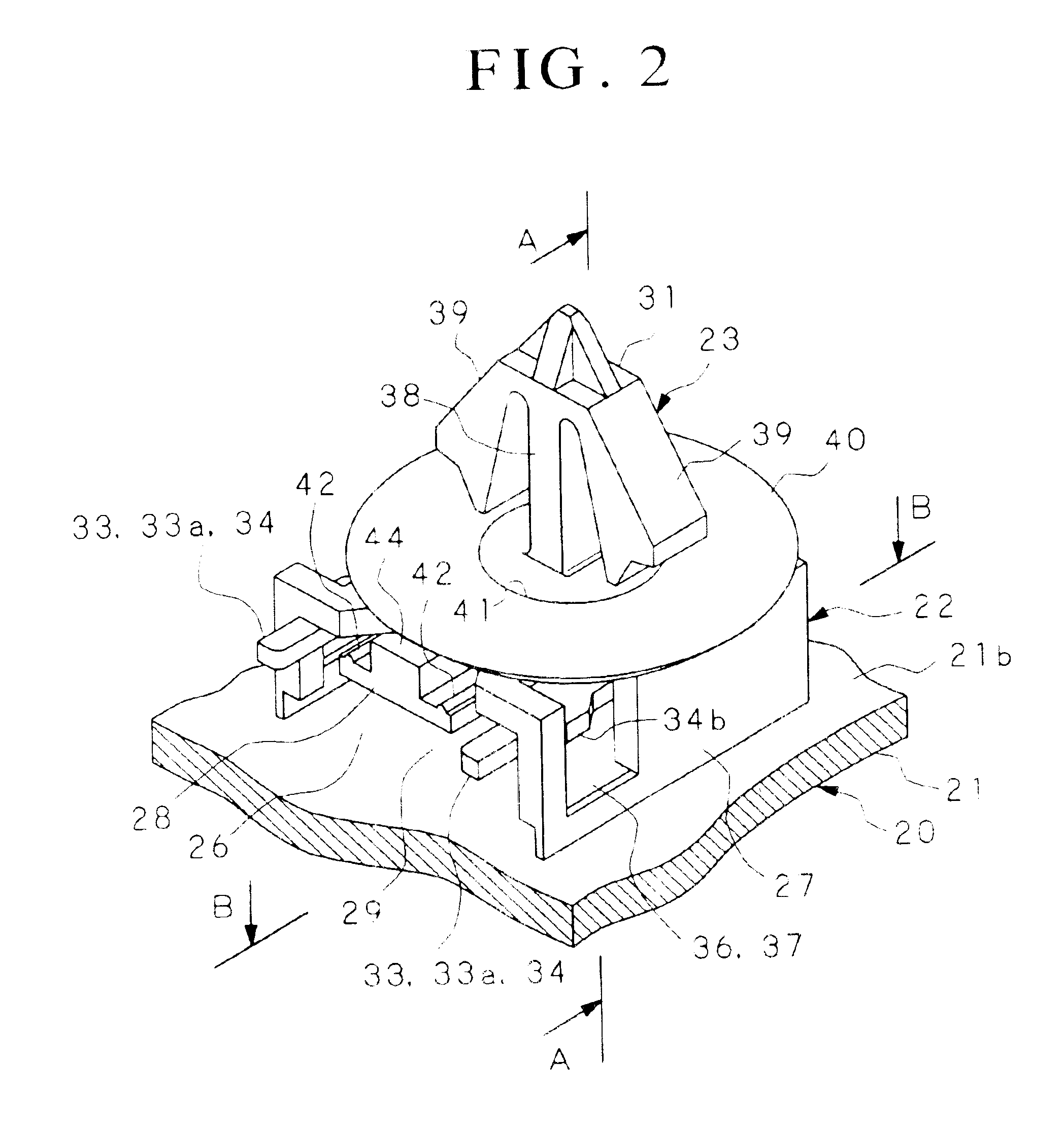
[0060]FIG. 1 is an exploded perspective view showing a fastener holder (clip holder, fastening portion holder) 22, which is provided to the molding main body 21 of a car molding 20, and a fastener (clip, fastening portion) 23, which is inserted and fastened into fastener holder 22, in the present invention. FIG. 2 is a perspective view showing an arrangement in which fastener 23 has been inserted and clipped into the fastener holder 22 shown in FIG. 1. FIG. 3 is a full perspective view looking at car molding 20 from the design face 21a side which forms the outer surface of molding main body 21. FIG. 4 is a perspective view showing an example of the mounting of car molding 20. FIG. 5 is a view showing the reverse face 21b, which is opposite design face 21a, of molding main body 21 of car molding 20.

[0061]As shown in FIGS. 1 through 5, car molding 20 is provided with a el...


PUM


Abstract

The present invention addresses the demand for a technology that enables reutilization of a molding main body and the fasteners for fixing a molding main body to an automobile following the removal of these parts from one another. The present invention proposes a car molding and fastener, in which a base plate is provided to a fastener for fixing molding main body to a car body, base plate being inserted into and held in place in housing space of a fastener holder that is formed to molding main body. Elastic pieces are provided on opposite sides of base plate, and have protruding portions which engage in a releasable manner with engage-and-stop portions on either side of fastener holder. By manipulating these elastic pieces, the aforementioned engagement is released, so that fastener can be separated from fastener holder in this car molding.

Description

BACKGROUND OF THE INVENTION[0001]1. Field of the Invention[0002]The present invention relates to an automobile molding and to a fastener for attaching this molding to a car body.[0003]2. Description of the Related Art[0004]So-called “fastener-held automobile molding,” such as employed in body-side, roof or bumper molding, has been proposed, for example, in Japanese Patent Application No. Hei 9-226476 (see FIGS. 12 and 13). When attaching this type of molding to a car body, a fastener 8, which has engaging claws 7 that project from its tip for engaging into a mounting hole in the car body, is engaged and clipped into a fastener holder 6. Fastener holder 6 is formed of three projecting walls 4, which project out from the molding main body 1 surface that is opposite the design face which will be on the outside of the car (i.e., projecting walls 4 are provided to the surface of the molding that will face the car, hereinafter referred to as “reverse face 2”), projecting walls 4 forming t...

Claims


Application Information

Patent Timeline
Patent Type & Authority Patents(United States)
IPC IPC(8): E04C2/38B60R13/04
CPCB60R13/04Y10T24/309Y10T24/303Y10T24/304
Inventor YOYASU, MASAE
Owner FALTEC CO LTD
Why Eureka
Try Eureka