
Method and apparatus for bone fracture fixation

a bone fracture and fixation technology, applied in the field of surgical applications, can solve the problems of affecting the purchase of fasteners, many known systems require time-consuming attachment, and system is still susceptible, so as to reduce the width of the bridge region in the cutting device, and reduce the risk of fractur

Inactive Publication Date: 2005-03-24
BIOMET MICROFIXATION
View PDF48 Cites 247 Cited by
  • Summary
  • Abstract
  • Description
  • Claims
  • Application Information

AI Technical Summary

Benefits of technology

"The present patent is about an apparatus and method for reapproximating and securing portions of severed bone using a bone reapproximation device and a plate with at least two bone fixation regions and a bridge region disposed between them. The fasteners used are bio-resorbable and / or bio-compatible. The plate can be easily removed from the bone surface without requiring removal of the main body portion of the fastener from the bone. The plate can also be severed using surgical scissors, wire cutters, or plate cutters. The plate has numerous bridge regions and bone fixation regions arranged in a variety of shapes to allow for coupling of large or irregularly shaped regions of severed bones. The technical effects of this patent are improved bone reapproximation and securement with reduced risk of complications and improved outcomes."

Problems solved by technology

While known systems utilizing plates and fasteners for aiding the osteosynthesis of severed bone regions have proven to be acceptable for certain applications, such systems are nevertheless susceptible to improvements that may enhance their performance.
In this regard, many known systems require time consuming attachment.
Additionally, known systems, which necessitate the insertion, removal, and subsequent reinsertion of fasteners into the bone, negatively affect fastener purchase.
Furthermore, many known systems do not facilitate cutting of the plate to provide expedited physician access to the area or cavity requiring access through the location spanned by the plate.

Method used


Image

  • Method and apparatus for bone fracture fixation
  • Method and apparatus for bone fracture fixation
  • Method and apparatus for bone fracture fixation

Examples


Embodiment Construction

The following description is merely exemplary in nature and is in no way intended to limit the teachings, its application, or uses.

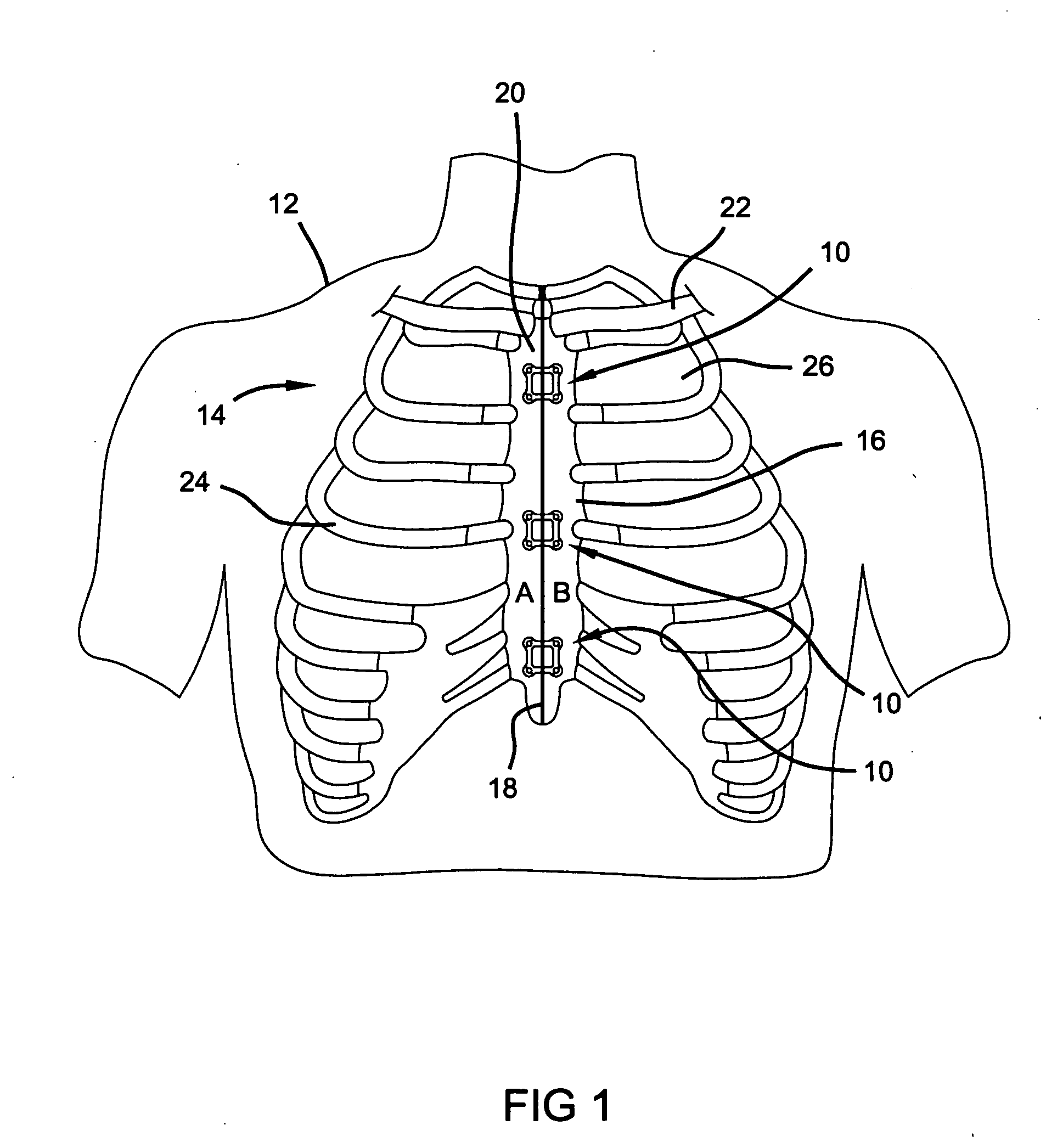
Referring to FIG. 1, a system constructed in accordance with the present teachings is generally identified with reference numeral 10. The system 10 is shown operatively associated within a human body 12 and specifically a human thorax 14. However, it will become apparent to those skilled in the art that certain aspects of the present teachings have applicability to other surgical applications.

The anterior of the thorax 14 is formed by a sternum 16, xyphoid 18, manubrium 20, costal cartilage, and ribs 24. In addition, the clavicle 22 is shown connecting the sternum 16 to the scapula and humerus (neither shown). The sternum 16, as shown, has previously undergone a medical procedure known as a median sternotomy. As a result of this procedure, the sternum 16 has been severed, thus permitting physician access to the tissues or organs located in thoracic ...


PUM


Abstract

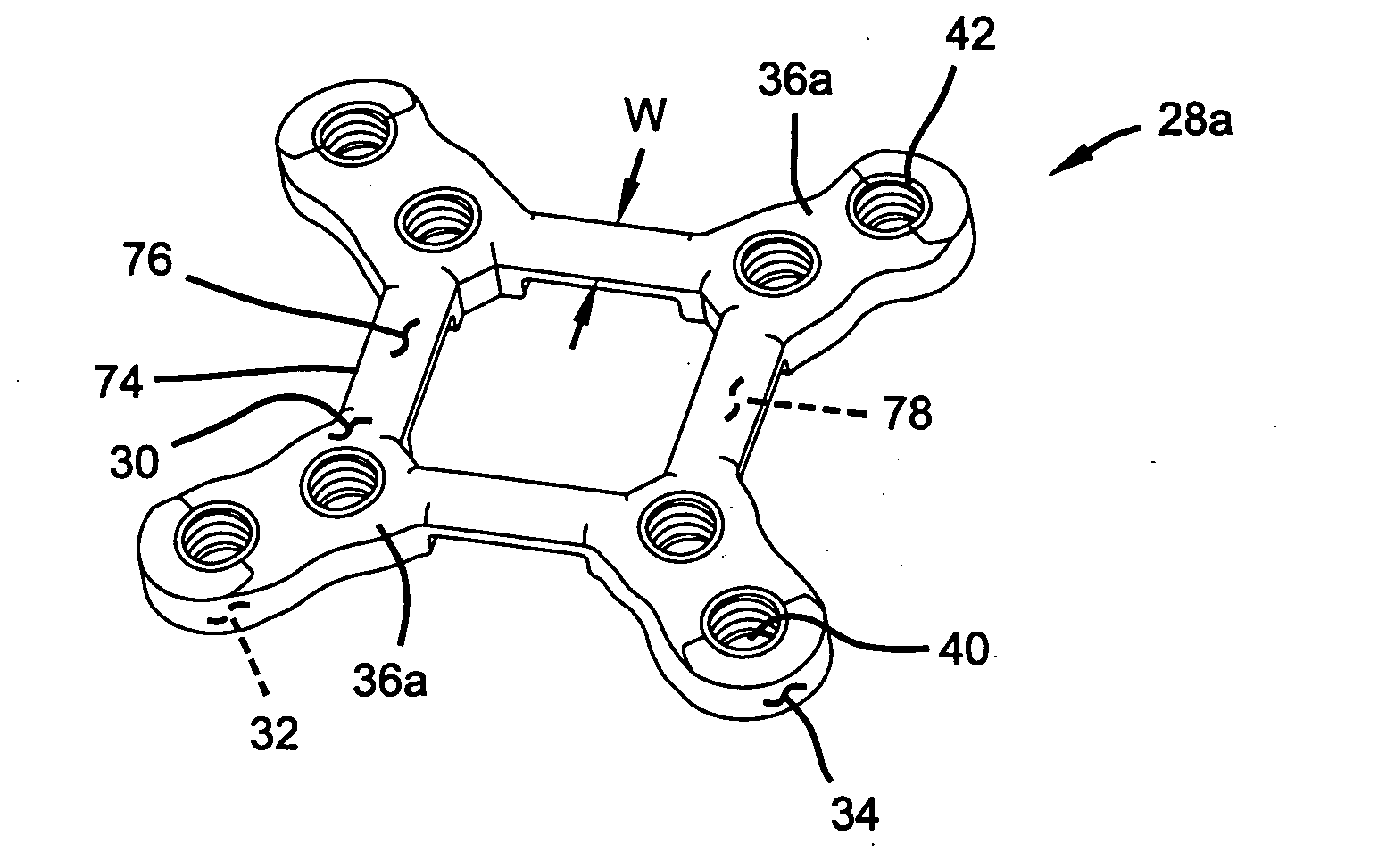
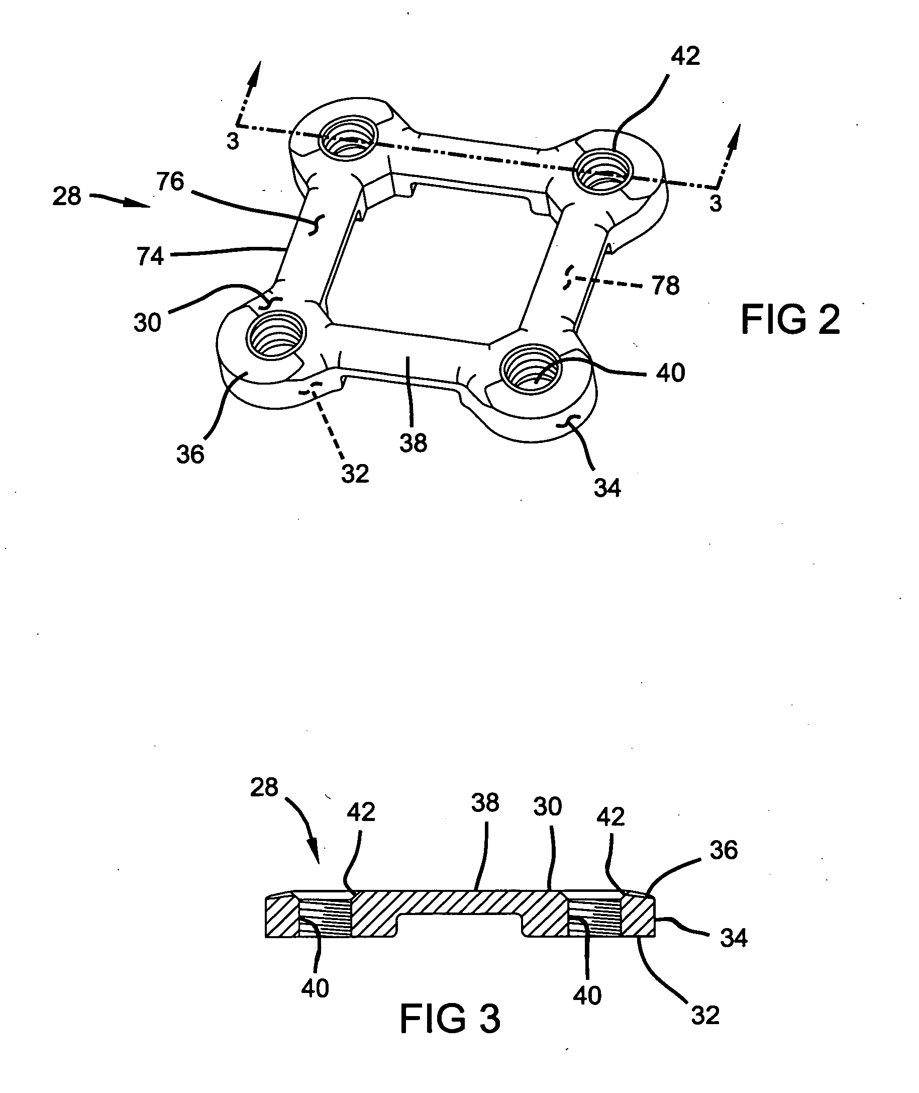
A plate for coupling severed bone regions comprising at least one bridge region, the at least one bridge region terminating in at least two bone fixation regions. The at least two bone fixation regions each contain at least one aperture for receiving a suitable fastening device for securing the plate to the bone regions to be coupled. The bridge region may be configured so as to be easily severed by a suitable severing device such as surgical scissors. The plate and fastening device may be formed from a bio-compatible or bio-resorbable material.

Description

FIELD The present teachings relate to surgical applications for the repair of bone fractures and deformities. More particularly, the teachings relate to a method and apparatus for securing two severed bone portions in a relatively fixed relationship to each other. BACKGROUND In various orthopedic surgical procedures, it is necessary to align and secure two severed bone portions in a relatively fixed relationship to each other. For example, it is often necessary to establish such a secured relationship after a bone has been fractured as a result of either natural causes or physician intervention. To ensure that the bone can regenerate in the proper orientation and fuse the fracture, it is important that the bone portions be fixed in the desired position during bone regeneration. It is known in the art to provide metal plates for the repair of bone fractures. The plates are generally secured to the fractured bone portions with fasteners such as screws. Among other applications, the...

Claims


Application Information

Patent Timeline
Patent Type & Authority Applications(United States)
IPC IPC(8): A61B17/00A61B17/58A61B17/80A61B17/86A61B17/88
CPCA61B17/80A61B17/8047A61B17/8052A61B2017/00004A61B17/8685A61B17/8863A61B17/8076
Inventor STEGER, SHON D.SCHUMACHER, BRIAN S.DUNCAN, JEFFREY A.
Owner BIOMET MICROFIXATION
Learn More