Encapsulated stent

a stent and stent technology, applied in the field of encapsulated stents, can solve the problems of not showing a device, unable to disclose a reference, and unable to show other desirable features

Inactive Publication Date: 2002-05-07
BARD PERIPHERAL VASCULAR
View PDF2 Cites 282 Cited by
  • Summary
  • Abstract
  • Description
  • Claims
  • Application Information

AI Technical Summary

Problems solved by technology

However, once such grafts are radially expanded within a blood vessel, they exhibit some retraction subsequent to expansion.
However, although stents and stent / graft combinations have been used to provide endovascular prostheses which are capable of maintaining their fit against blood vessel walls, other desirable features are lacking.
Although the previously described reinforced grafts disclose structures which have increased strength and durability, as well as inert, smooth inner and outer surfaces to reduce thrombogenicity, the prior art references do not disclose a device which exhibits these advantageous characteristics in addition to good resistance to radial contraction and possible self anchoring means.

Method used


Image

  • Encapsulated stent
  • Encapsulated stent
  • Encapsulated stent

Examples


example 2

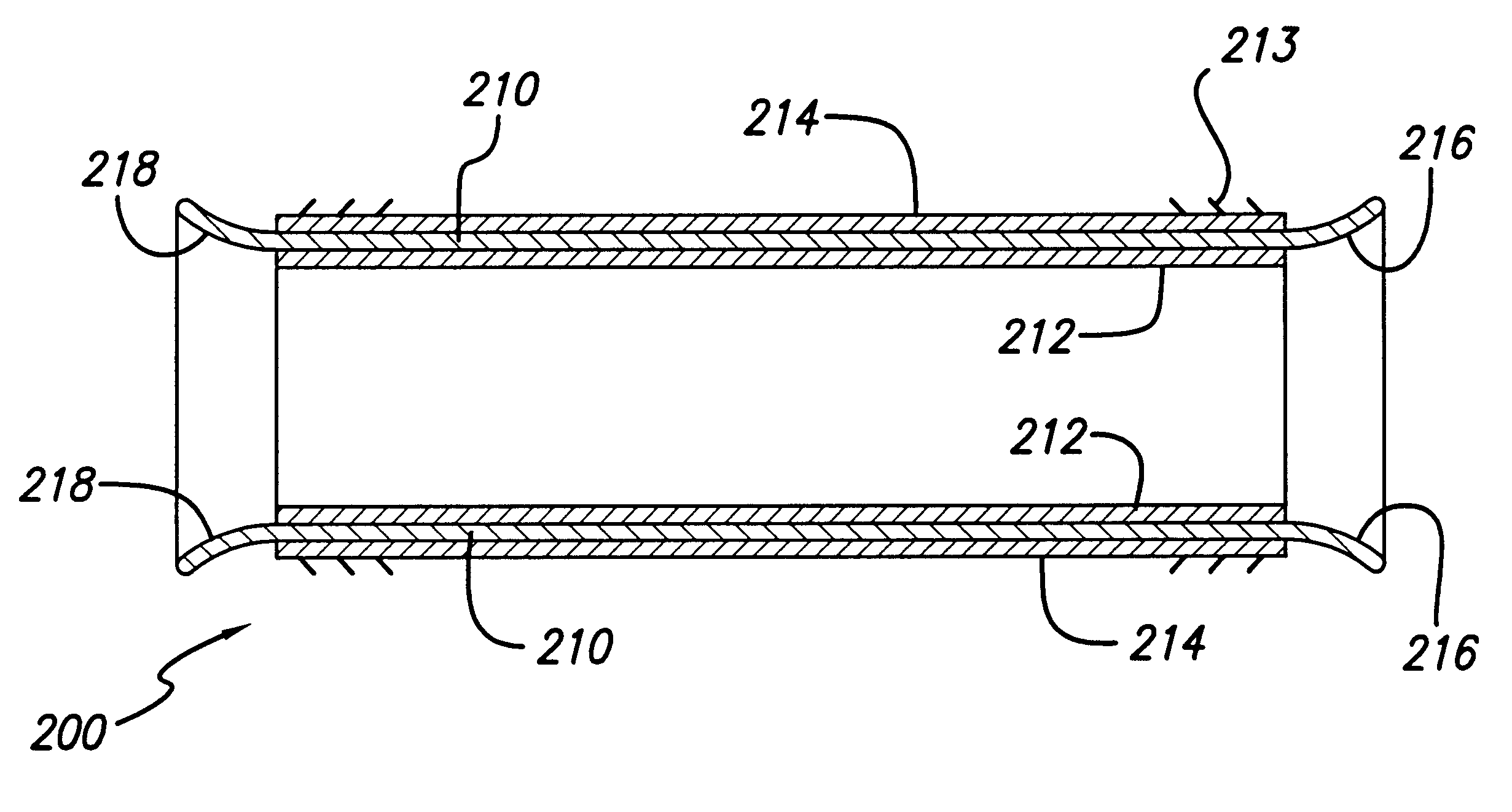
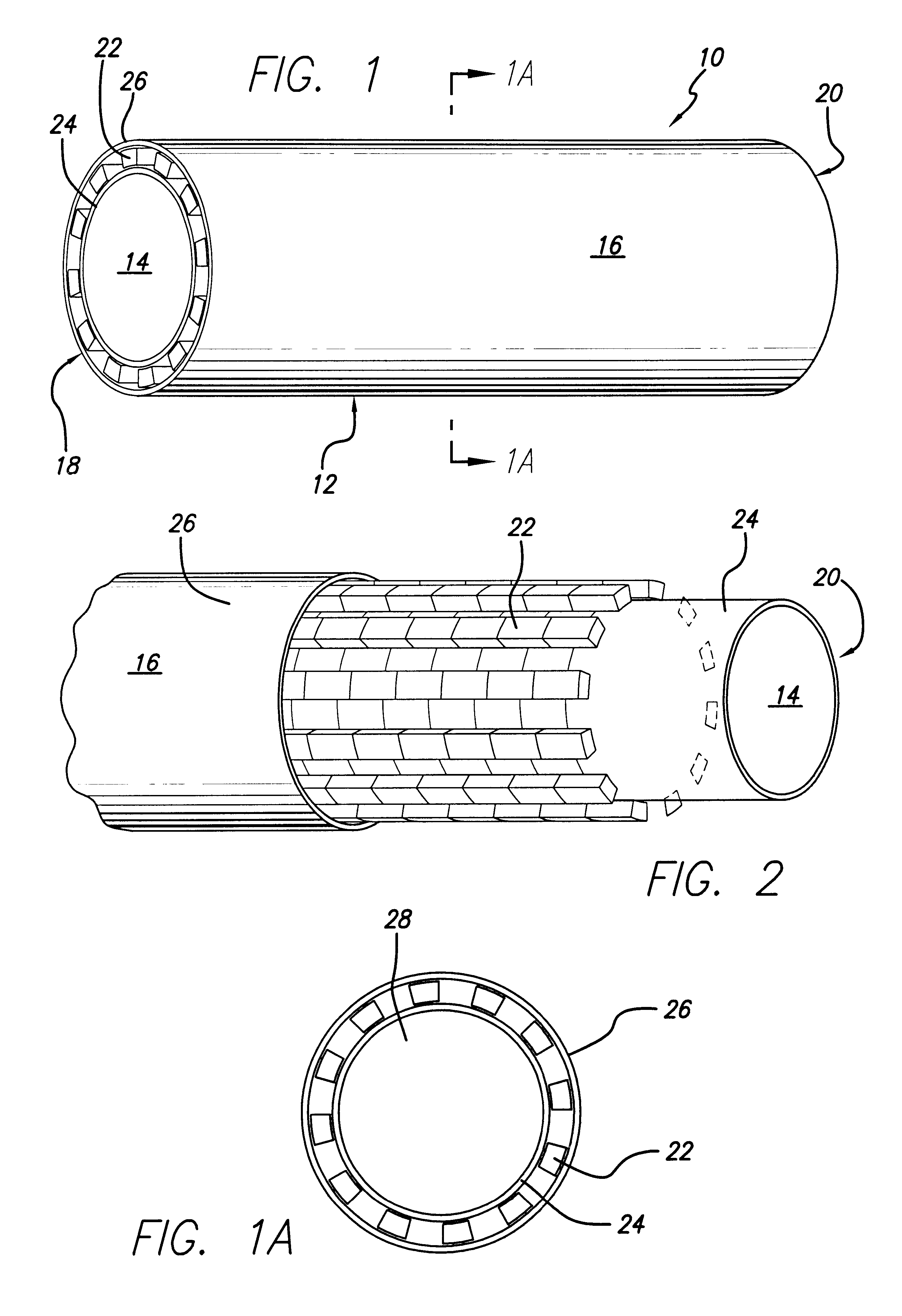
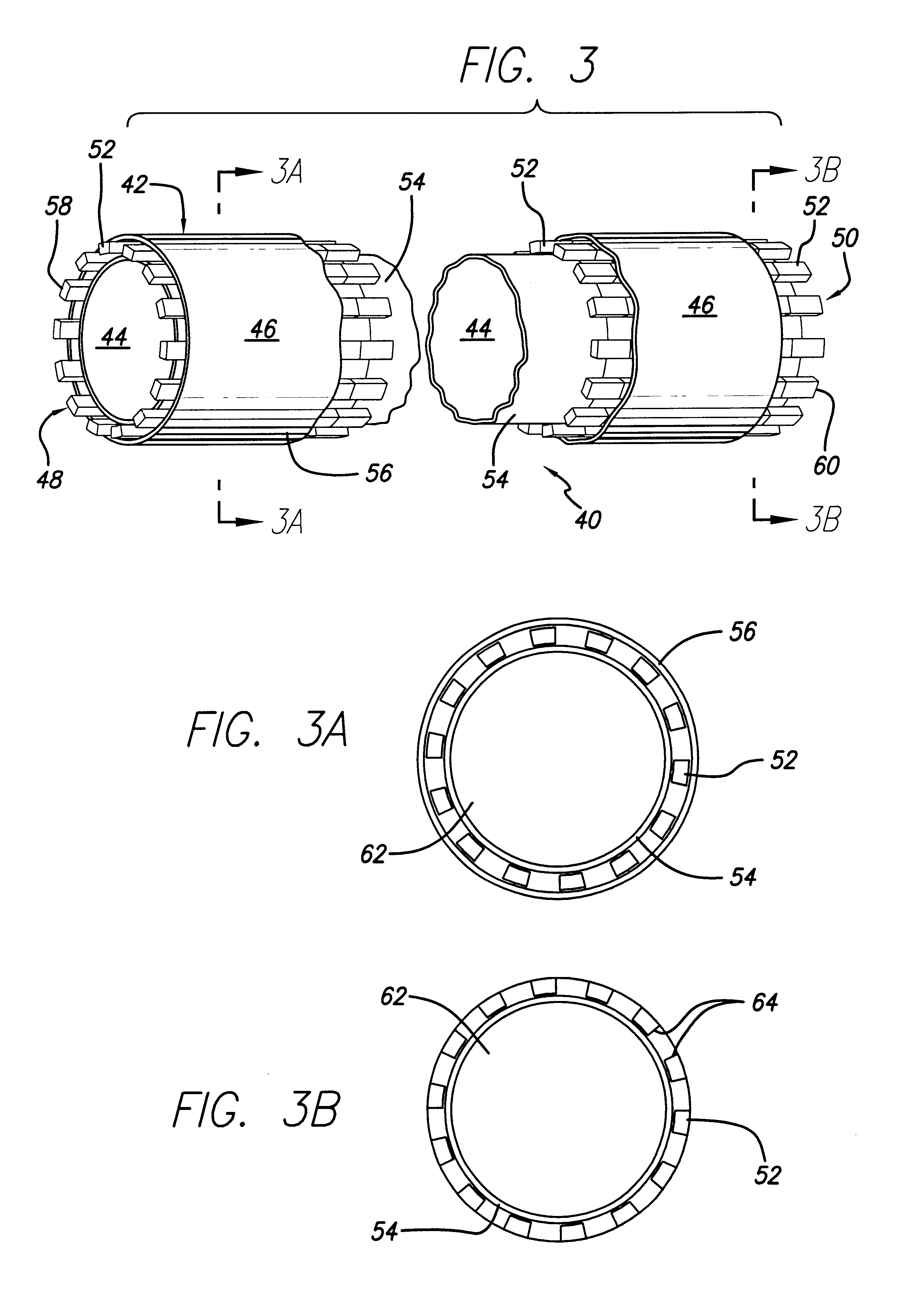
A 3 mm ID thin wall ePTFE graft was loaded onto a 3.56 mm mandrel. The top section of the 3 mm, ePTFE graft was wrapped with TEFLON tape to prevent migration. Next, three P-394 "PALMAZ" stents and three P-308 "PALMAZ" stents were pre-dilated on a 4.74 mm mandrel. The three P-394 pre-dilated stents were loaded first onto the 3 mm ePTFe graft, followed by the three P-308 pre-dilated stents, and then spaced equidistantly from another along the length of the 3 mm ePTFE graft. The predilated stents were then crimped onto the mandrel and a 4 mm ID ePTFE graft was loaded over the crimped stents. The 4 mm ePTFE graft was wire wrapped at both its ends and between the crimped stents. The entire assembly was then placed in an oven for 30 seconds and heated at 340.degree. C. and then removed. The assembly was then wrapped tightly with TEFLON tape with the three P-308 stents being wrapped first. The entire TEFLON tape wrapped assembly was then heated at a sintering temperature of 375.degree. C. ...


PUM


Abstract

An encapsulated stent having a stent or structural support layer sandwiched between two biocompatible flexible layers. One preferred embodiment has a stent cover which includes a tubular shaped stent that is concentrically retained between two tubular shaped grafts comprised of expanded polytetrafluoroethylene. Another preferred embodiment has a stent graft which includes at least one stent sandwiched between the ends of two tubular shaped grafts wherein at least a portion of the grafts are unsupported by the stent. Still another embodiment includes an articulating stented graft which includes a plurality of stents spaced apart from one another at a predetermined distance wherein each stent is contained between two elongated biocompatible tubular members. The graft/stent/graft assemblies all have inseparable layers.

Description

1. Field of the InventionThe present invention relates generally to an encapsulated stent comprising a stent inseparably contained between two grafts wherein the, grafts are preferably comprised of expanded polytetrafluoroethylene (ePTFE) and, in addition, to a method for making an encapsulated stent. More particularly, one preferred embodiment of the present invention relates to a radially expandable encapsulated stent for implantation within the vascular system which comprises a balloon expandable tubular stent member which is sandwiched between two tubular shaped ePTFE members. The tubular shaped members may also be comprised of unexpanded polytetrafluoroethylene (ePTFE). The method for making the encapsulated stent includes concentrically positioning the stent between the graft members, applying pressure to the assembly to fuse the graft layers to one another through the openings between the struts of the stent, and sintering the assembly.2. Description of Related ArtThe use of ...

Claims


Application Information

Patent Timeline
Patent Type & Authority Patents(United States)
IPC IPC(8): A61F2/06
CPCA61F2/07A61F2/90A61F2002/072
Inventor BANAS, CHRISTOPHER E.EDWIN, TARUN J.
Owner BARD PERIPHERAL VASCULAR
Why Eureka
Try Eureka