Implantable prosthetic valve

a prosthetic valve and implantable technology, applied in the field of implantable prosthetic valves, can solve the problems of potentially life-threatening conditions, insufficiency of the venous system of the limb, and loss of effectiveness

Inactive Publication Date: 2011-05-24
CLINASYS
View PDF20 Cites 14 Cited by
  • Summary
  • Abstract
  • Description
  • Claims
  • Application Information

AI Technical Summary

Benefits of technology

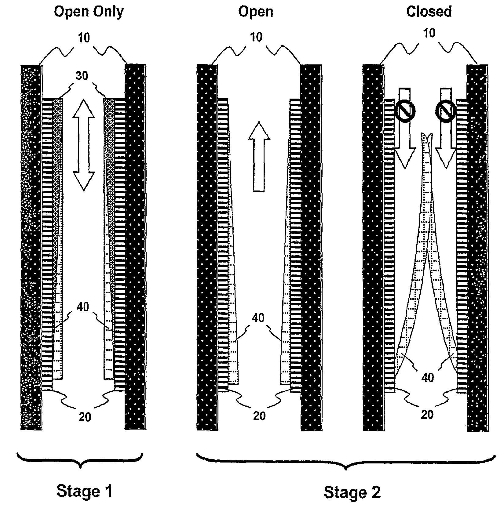
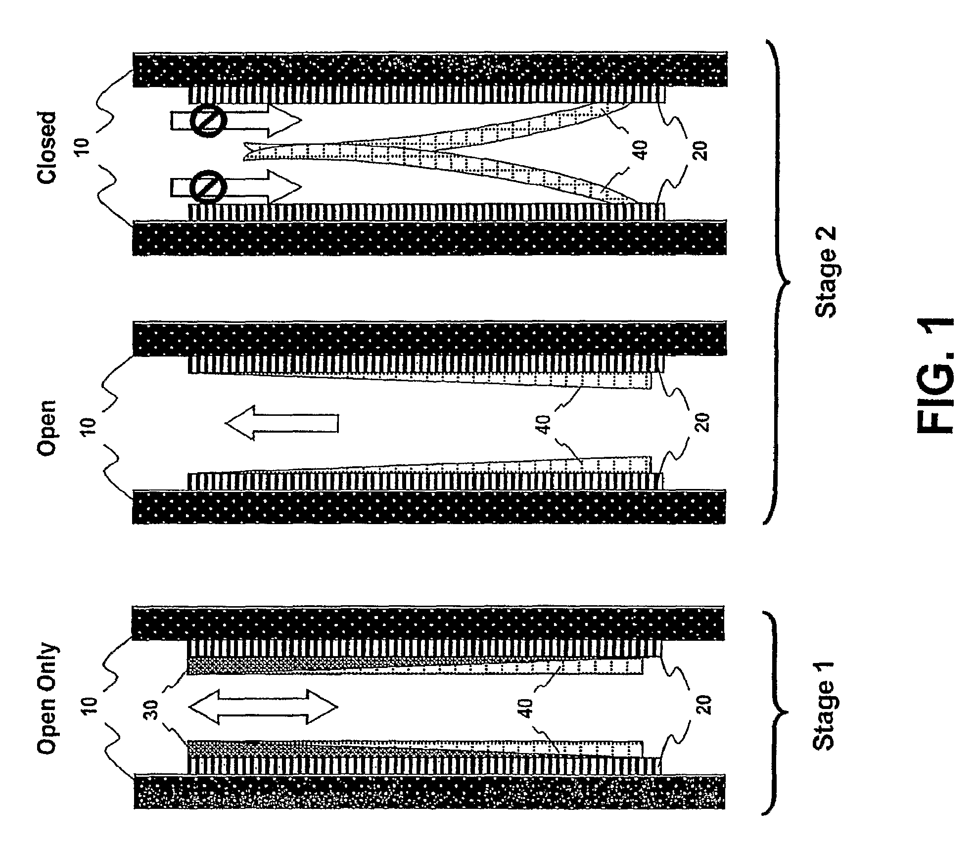
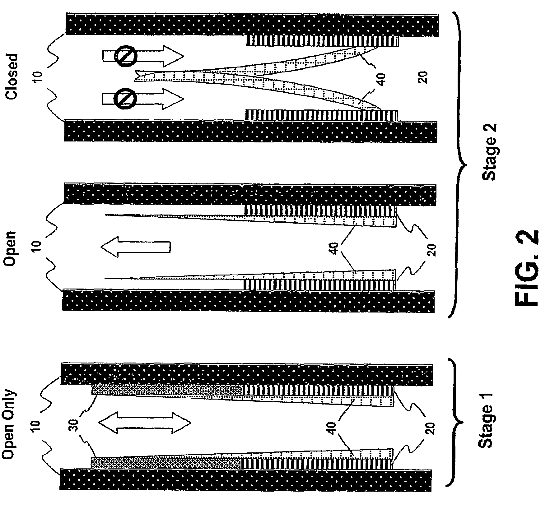
[0008]Prosthetic valves and methods are provided that delay the commencement of valving function and allow for a period of time in which the native vessel heals and recuperates after the intervention and before flow changes brought about by functioning valve leaflets set in.
[0009]In various embodiments, the prosthetic valve and methods allow for natural growth of cells and tissue over the implanted prosthesis, which may reduce the implant's thrombogenicity and, in turn, may increase prosthetic valve survival by limiting the presence of key thrombogenic factors (e.g. flow changes leading to abnormal thrombogenic flow patterns, implant thrombogenicity) in the time period immediately following prosthetic valve implantation.
[0010]In various embodiments, the prosthetic valve becomes more biocompatible by allowing cell deposition, tissue growth and remodeling into a partially or completely biological functioning valve.

Problems solved by technology

Unfortunately, native valves may lose their effectiveness leading to potentially life threatening conditions.
For example, over time, the vessel wall may stretch, or the leaflet may become damaged due to disease or occlusion affecting the valve leaflet's ability to close resulting in changes in fluid flow, which may lead to, in severe cases, the insufficiency of the venous system of a limb and the pain, swelling, ulcers, thrombosis, a loss of quality of life, disability and even death.
A conventional prosthetic valve that stayed restrained in one position regardless of the fluid pressure would be considered defective and, if implanted in the body, may need to be removed.
Other factors that may lead to thrombosis include excessive trauma to the vessel's intima during implantation and the particular materials used to make the valve that may be thrombogenic.
These factors (e.g., gross flow changes that may include thrombogenic turbulent flow, thrombogenicity of the valve, and trauma to the implantation site) all reduce prosthetic valve survival.
Indeed, today there is no commonly accepted and widely used prosthetic venous valve available to the practicing physician, as most valve designs fail after implantation, primarily due to thrombosis (blood clot formation).

Method used


Image

  • Implantable prosthetic valve
  • Implantable prosthetic valve
  • Implantable prosthetic valve

Examples


Embodiment Construction

[0027]Reference will now be made in detail to certain embodiments of the invention, examples of which are illustrated in the accompanying drawings. While the invention will be described in conjunction with the illustrated embodiments, it will be understood that they are not intended to limit the invention to those embodiments. On the contrary, the invention is intended to cover all alternatives, modifications, and equivalents, which may be included within the invention as defined by the appended claims.

[0028]It is noted that, as used in this specification and the appended claims, the singular forms “a,”“an,” and “the,” include plural referents unless expressly and unequivocally limited to one referent. Thus, for example, reference to “a leaflet” includes one, two, three or more leaflets.

[0029]The headings below are not meant to limit the disclosure in any way; embodiments under any one heading may be used in conjunction with embodiments under any other heading.

[0030]In various embod...


PUM


Abstract

An implantable prosthetic valve for regulating fluid flow through a body vessel is provided. The prosthetic valve comprises an anchoring member, at least one leaflet, and a restraining member capable of temporarily preventing substantial movement of the leaflet between and open and closed position so as to allow fluid flow in the antegrade and retrograde directions. In various embodiments, the prosthetic valve reduces the risk of thrombosis. In various embodiments, the prosthetic valve reduces the appearance of potentially thrombogenic abnormal flow patterns at the site of implantation immediately following the implantation, allows cell deposition making the valve more biocompatible, less thrombogenic before flow changes resulting from valving action set in and allows tissue growth so that a partially or completely biological functioning valve may form on the scaffold provided by the implant.

Description

BACKGROUND OF THE INVENTION[0001]Prosthetic valves have proven to be a most beneficial treatment option in replacing diseased or malfunctioning native valves. Over the years, prosthetic heart valves have saved hundreds of thousands of lives. Prosthetic venous valves promise a treatment option for a large group of patients suffering from the consequences of lost or damaged valves, for example, in their deep veins.[0002]Native valves have leaflets that act as one-way check valve and open to permit fluid flow through vessels in the forward or antegrade direction and close to substantially prevent fluid flow in a reverse or retrograde direction. Leaflets can change from an open position in response to a variety of circumstances, including changes in the cross-sectional shape of the vessel, and the fluid pressure within the vessel.[0003]Unfortunately, native valves may lose their effectiveness leading to potentially life threatening conditions. For example, over time, the vessel wall may...

Claims


Application Information

Patent Timeline
Patent Type & Authority Patents(United States)
IPC IPC(8): A61F2/24A61F2/06
CPCA61F2/2418A61F2/2475A61F2250/0031A61F2220/0066A61F2220/0008A61F2220/0016A61F2220/0041A61F2250/0071A61F2/0077
Inventor MERETEI, ATTILA
Owner CLINASYS
Why Eureka
Try Eureka