
Micro nozzle assembly

a technology of micro nozzles and nozzles, which is applied in the direction of inhalators, medical devices, other medical devices, etc., can solve the problems of difficult to position the die in the holder with a high degree of precision, increase the risk of bacteria ingrowth through the nozzle into the liquid reservoir, and other problems

Pending Publication Date: 2021-07-22
SHL MEDICAL AG
View PDF0 Cites 1 Cited by
  • Summary
  • Abstract
  • Description
  • Claims
  • Application Information

AI Technical Summary

Benefits of technology

The present invention provides a carrier assembly with a micro nozzle that can be easily handled for assembly with a spray device. The carrier assembly allows for a residual spray liquid to escape or be easily cleaned out. The attachment of the micro nozzle to the carrier member also allows air to flow around the outlet orifice of the micro nozzle, which is beneficial in inhalation applications. The carrier assembly provides a stable seat for the micro nozzle with corresponding angles.

Problems solved by technology

Obviously, problems are encountered when such small components are to be assembled with the spray device.
However, it is difficult to position the die in the holder with a high degree of precision.
In addition, the assembly of the die and the holder results in a depression at an outlet surface of the nozzle, where the thermoplastic holder forms the side walls of the depression.
When the nozzle is in use, residual spray liquid may accumulate in the depression and cause clogging of the orifices, and may increase the risk of ingrowth of bacteria through the nozzle into the liquid reservoir on the other side of the nozzle, which is particularly disadvantageous when the liquid reservoir is the primary medicament container of a medicament delivery device, e.g. an inhalation device.

Method used


Image

  • Micro nozzle assembly
  • Micro nozzle assembly
  • Micro nozzle assembly

Examples


Embodiment Construction

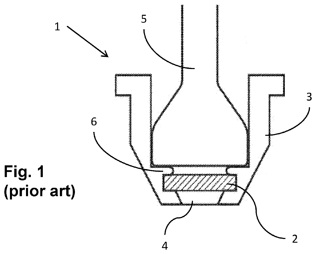
[0054]A cross section view of a prior art micro nozzle assembly 1 is shown in FIG. 1. A micro nozzle 2 has been heated and pushed into a tapered seat of a thermoplastic holder 3. FIG. 1 shows the subsequent step where a thermode 5 is pressed into the seat behind the nozzle to create a rivet-like flange 6 of the thermoplastic material, which further secures the micro nozzle in the seat. As can be seen, a depression 4, or cavity, is formed in the holder 3 in front of the nozzle 2. Such a depression may accumulate spray liquid, which may dry, or solidify, and may clog orifices of the micro nozzle 2. The accuracy of the positioning of the micro nozzle 2 in the holder according to this method is further unsatisfactory. It is an object of the present disclosure to improve on these issues.

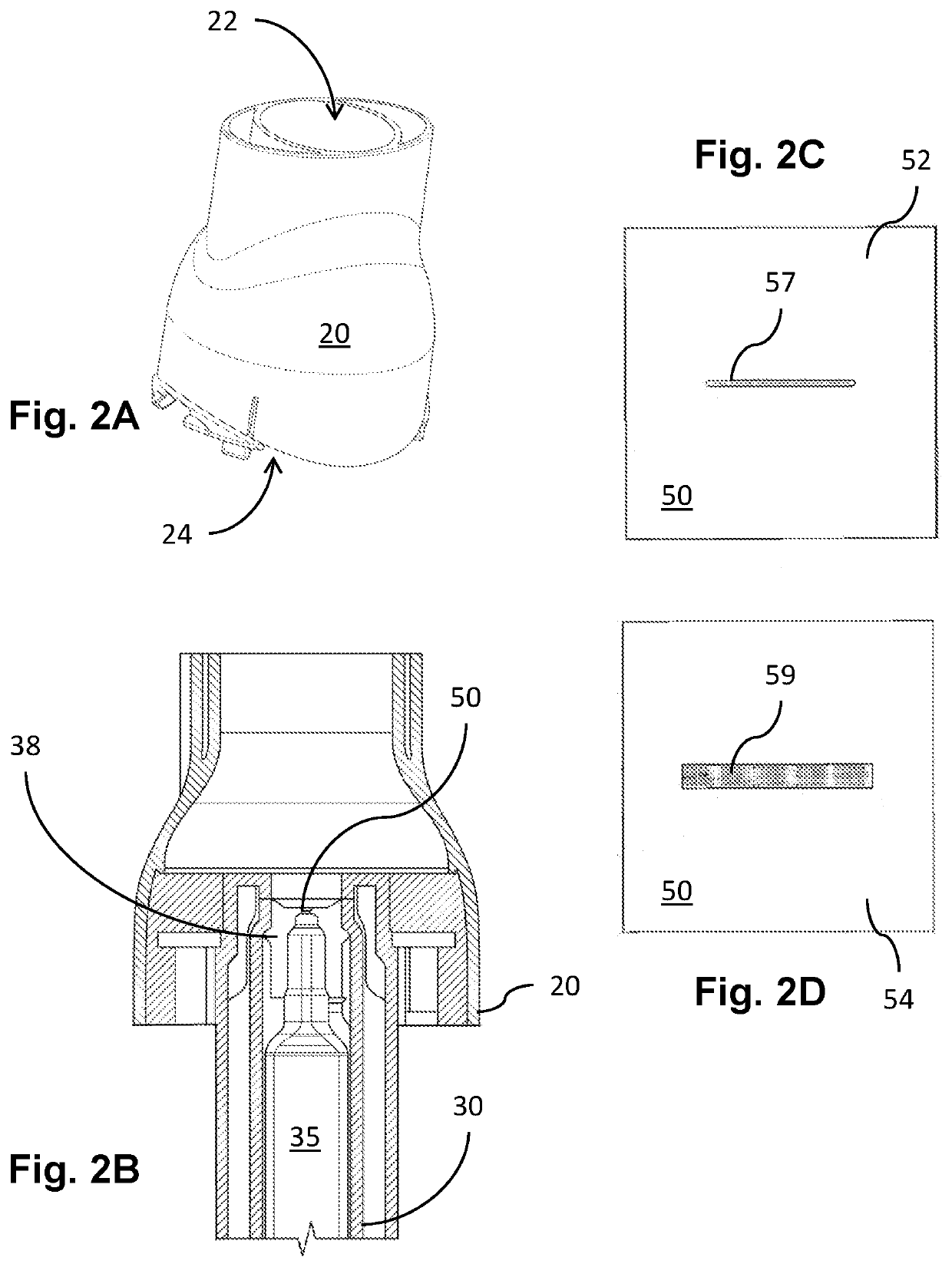
[0055]FIG. 2a shows a perspective view of an exemplary embodiment of a dispenser unit 20 of a spray device. A micro nozzle 50 (FIG. 2b) is mounted in the dispenser unit. The dispenser unit 20 has proximal...


PUM


Abstract

A carrier assembly for a spray device, which carrier assembly comprises a carrier member adapted to be mounted in a cartridge adapter of a spray device, which carrier member has a proximally directed first surface, and a through-hole placing the first surface in fluid communication with the second surface; a micro nozzle having an outlet surface, an inlet surface, and a channel placing an inlet orifice at the inlet surface in communication with an outlet orifice at the outlet surface and wherein the micro nozzle is accommodated and attached to the carrier member such that the outlet orifice is aligned with the through-hole, and wherein the carrier member comprises vent holes formed to allow air to flow between the second surface and the first surface.

Description

TECHNICAL AREA[0001]The present disclosure relates to a micro nozzle assembly, and in particular to a micro nozzle assembled with a carrier member.BACKGROUND OF INVENTION[0002]There are many different kinds of spray devices on the market today. Micro nozzle devices comprising micro nozzles form an increasingly important and growing segment of the market. Micro nozzles may for instance be found in ink jet printing appliances, 3D printers, perfume containers and medicament delivery devices. Such nozzles comprise orifices for expelling the liquid spray, which orifices have diameters between 0.5 μm and 10 μm. To produce nozzles in the lower diameter range, the small dimensions require the orifices to be produced in micro technology processes, such as by etching channels in a semiconductor wafer, which wafer is thereafter diced into individual nozzles. In order to increase the yield of each wafer, the nozzle dies are preferred to be made as small as possible, each typically having a surf...

Claims


Application Information

Patent Timeline
Patent Type & Authority Applications(United States)
IPC IPC(8): A61M15/00B05B15/65B05B1/14
CPCA61M15/009B05B15/65B05B1/14A61M15/0021A61M2205/0238A61M2205/0211A61M2205/0233A61M2206/11A61M15/002A61M2207/00A61M15/06A61M15/08A61M15/0065A61M2202/0468A61M11/005A61M2202/0007
Inventor SÄLL, DANIELMIDBJER, JOHANGYLLEBY, STEFANDIETL, THOMASMYRMAN, MATTIAS
Owner SHL MEDICAL AG
Learn More