
Wafer drying apparatus and method for drying a wafer

a drying apparatus and wafer technology, applied in electrical apparatus, basic electric elements, testing/measurement of semiconductor/solid-state devices, etc., can solve the problems of reducing the reliability of measurement, untried portion, etc., to prevent increase the weight of droplets, and reduce the movement of droplets

Active Publication Date: 2016-09-22
SHIN-ETSU HANDOTAI CO LTD
View PDF3 Cites 4 Cited by
  • Summary
  • Abstract
  • Description
  • Claims
  • Application Information

AI Technical Summary

Benefits of technology

The present invention provides a method for reducing the amount of undried portions on a wafer by increasing the weight of droplets on the surface of the wafer, which in turn facilitates their downward movement and drop from the wafer. As a result, the method prevents the droplets from adhering to the end face of the wafer and reduces the likelihood of defects caused by incomplete drying during the manufacturing process.

Problems solved by technology

However, when an intermediate examination is performed, an undried portion lowers reliability of a measurement result.

Method used


Image

  • Wafer drying apparatus and method for drying a wafer
  • Wafer drying apparatus and method for drying a wafer
  • Wafer drying apparatus and method for drying a wafer

Examples


examples

[0092]While the present invention will be described more specifically below using an example and a comparison example, the present invention is not limited to this.

example

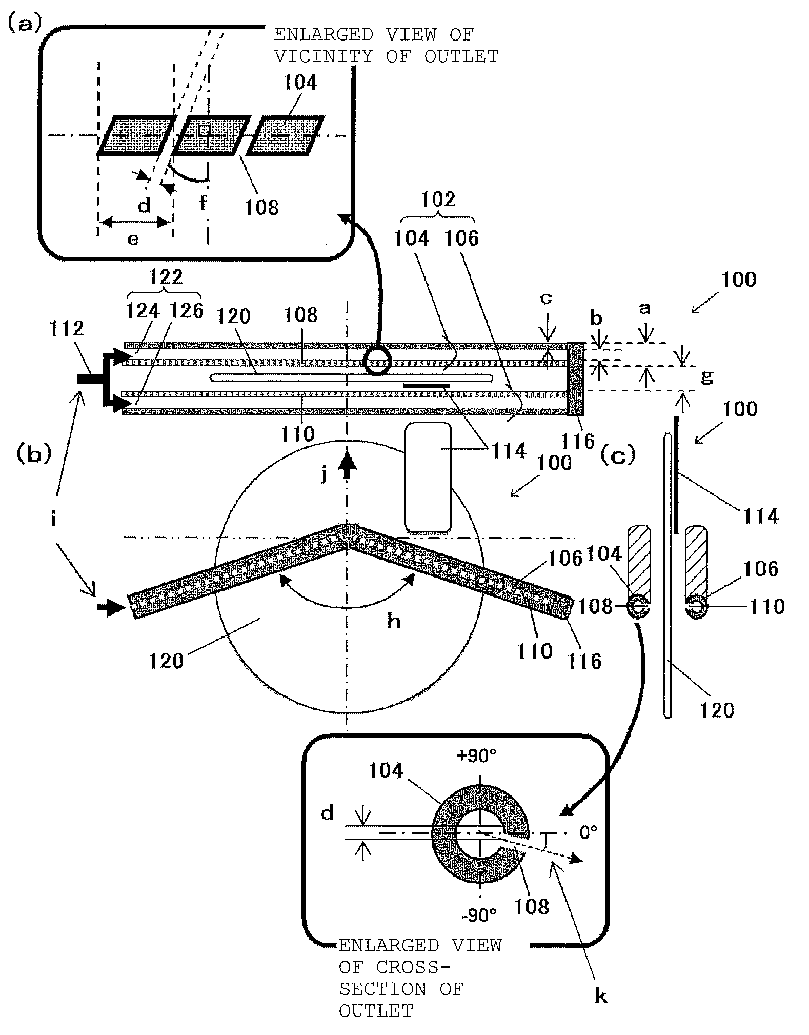
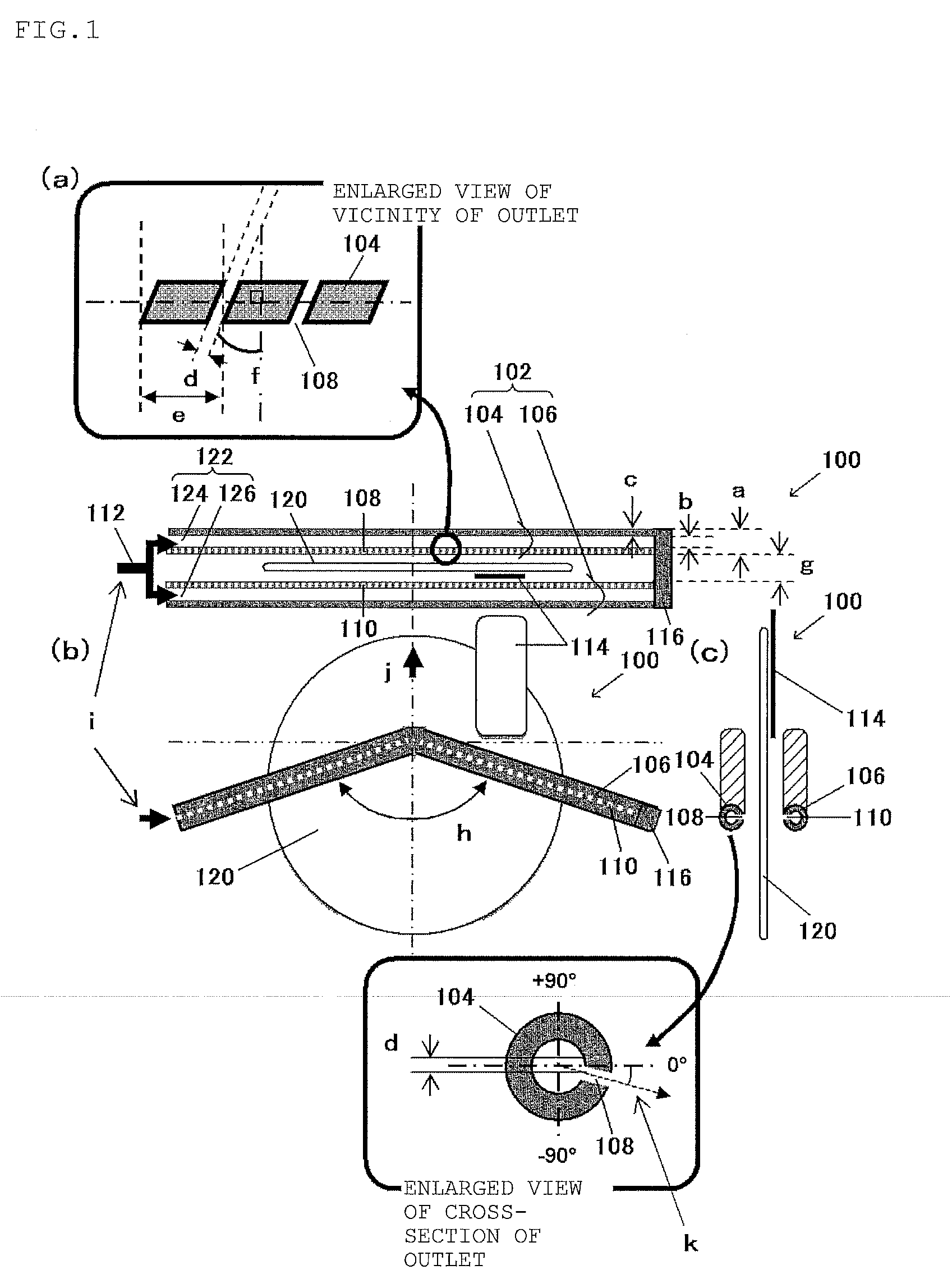
[0093]Both surfaces of a silicon wafer having a diameter of 300 mm were dried using the wafer drying apparatus 100 illustrated in FIG. 1 using the method for drying wafer described above. It should be noted that the silicon wafer is subjected to double-side polishing and is covered with a slurry including a polymer wetting agent.

[0094]Further, details of the wafer drying apparatus 100 being used will be described below.

[0095]Outer diameter a of air supply tube: 13 mm in diameter

[0096]Inner diameter b of air supply tube: 9 mm in diameter

[0097]Thickness c of air supply tube: 2 mm

[0098]Outlet diameter d: 1 mm in diameter

[0099]Outlet interval e: 5 mm

[0100]Outlet angle (horizontal direction) f: 15 degree

[0101]Interval g between air supply tubes: 15 mm at the central portion, 17 mm at the end portion

[0102]Bending angle h of the air supply tube: 165 degree

[0103]Air supply pressure: 0.5 MPa

[0104]Wafer moving velocity j: 25 mm / sec

[0105]Outlet angle (vertical direction) k: −5 degree


PUM

PropertyMeasurementUnit
outlet diameteraaaaaaaaaa
diameteraaaaaaaaaa

Abstract

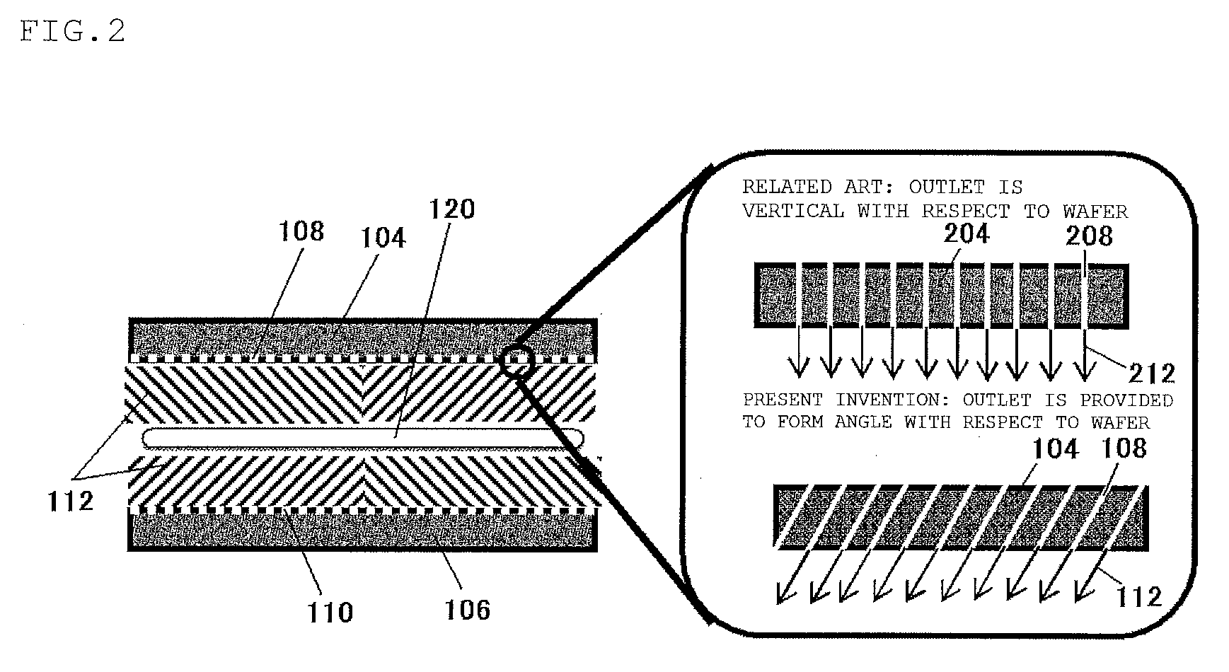
A wafer drying apparatus includes air supply unit having first and second air supply tube provided at respective first and second front-surface side of wafer, and wafer holding unit configured to vertically hold wafer, and configured so that wafer relatively moves with respect to air supply unit, plurality of first air outlets separated from each other at predetermined intervals are provided at wafer side of first air supply tube, plurality of second air outlets separated from each other at predetermined intervals are provided at wafer side of second air supply tube, plurality of first and second air outlets are respectively provided to form an angle with respect to vertical direction regarding wafer as to blow air from peripheral portion to central portion with respect to central line in vertical direction of wafer. It is possible to provide wafer drying apparatus with simple structure, which reduces undried portion without degrading productivity.

Description

BACKGROUND OF THE INVENTION[0001]1. Field of the Invention[0002]The present invention relates to a wafer drying apparatus which performs drying processing on a wafer such as a semiconductor wafer and a method for drying a wafer using the wafer drying apparatus, and, more particularly, a wafer drying apparatus which performs drying by blowing air to a wafer and a method for drying a wafer using the wafer drying apparatus.[0003]2. Description of the Related Art[0004]Conventionally, both surfaces of a square substrate such as a liquid crystal substrate subjected to wet surface treatment have been dried by blowing air to the square substrate from a slit-shaped gas jetting port while the square substrate are horizontally conveyed (see, for example, Patent Literature 1 and Patent Literature 2).[0005]Further, silicon wafer processing process also includes process of performing drying processing. For example, in process in which a slurry, drug solution, or the like, is used, a wafer gets we...

Claims


Application Information

Patent Timeline
Patent Type & Authority Applications(United States)
IPC IPC(8): H01L21/67
CPCH01L22/10H01L21/67034H01L22/12
Inventor YASUDA, TAICHIENOMOTO, TATSUO
Owner SHIN-ETSU HANDOTAI CO LTD
Learn More