Turboalternator with hydrodynamic bearings

a technology of hydrodynamic bearings and alternators, which is applied in the direction of electric generator control, separation process, liquid degasification, etc., can solve the problems of oil contamination of process gas, unreliable oil-lubricated bearings used in the device of u.s. pat. no. 5,045,711, and other problems, to achieve the effect of improving system overall efficiency, recovering energy, and recovering energy

Active Publication Date: 2008-10-09
R & D DYNAMICS
View PDF67 Cites 117 Cited by
  • Summary
  • Abstract
  • Description
  • Claims
  • Application Information

AI Technical Summary

Benefits of technology

[0025]Pressure Letdown Stations refers to commercial processing plants that use pressure reducing valves (PRV) to letdown the process gas (oftentimes steam) to lower pressure. An example is the production of cheese where 125 psig saturated stream is used for pasteurization, 80 psig for curd processing and <60 psig for mixing, drying and cleaning. Replacing the PRV with a turboalternator allows for recovery of otherwise wasted energy.
[0026]Waste Gas Energy Recovery (WGER) refers to the extraction of usable energy from industrial process gas that would otherwise be dumped to atmosphere. A turboalternator can be used to extract energy from low pressure gas to recover energy and improve system overall efficiency. An example of WGER is a turboalternator installed in the exhaust of an internal combustion engine used to generate electricity from the engines exhaust. A turboalternator could be used in series or parallel with a turbocharger.

Problems solved by technology

Unfortunately, oil-lubricated bearings as used in the device of U.S. Pat. No. 5,045,711 are unreliable, especially at the high running speeds more typical of and expected from modern turbomachinery devices.
Further, shaft seals tend to wear out quickly and oil contamination of the process gas becomes a significant problem.
Unfortunately, titling pad bearings still suffer from high power loss, mechanical complexity, pivot fretting, limited damping capacity and indirect measurement of bearing loading.
Heretofore, known problems with turboalternator devices arose due to the excessive size and complexity of such devices.
Low & High Temperature Capabilities—Many oil lubricants cannot operate at very high temperatures without breaking down.
At low temperature, oil lubricants can become too viscous to operate effectively.
Foil bearings, however, operate efficiently at severely high temperatures, as well as at cryogenic temperatures.

Method used


Image

  • Turboalternator with hydrodynamic bearings
  • Turboalternator with hydrodynamic bearings
  • Turboalternator with hydrodynamic bearings

Examples


Embodiment Construction

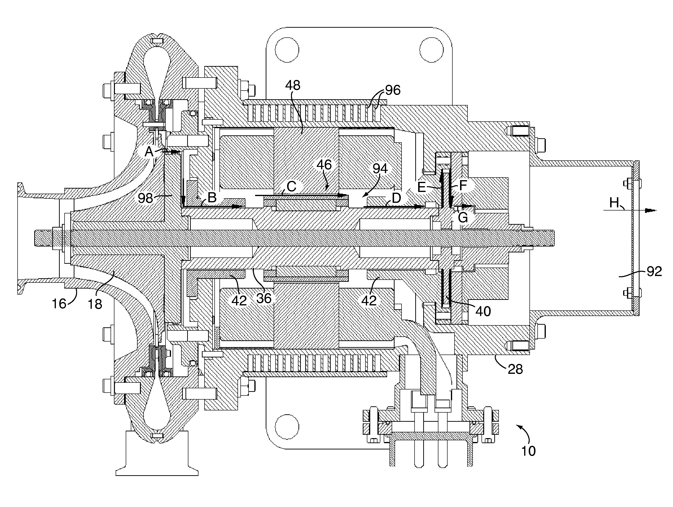
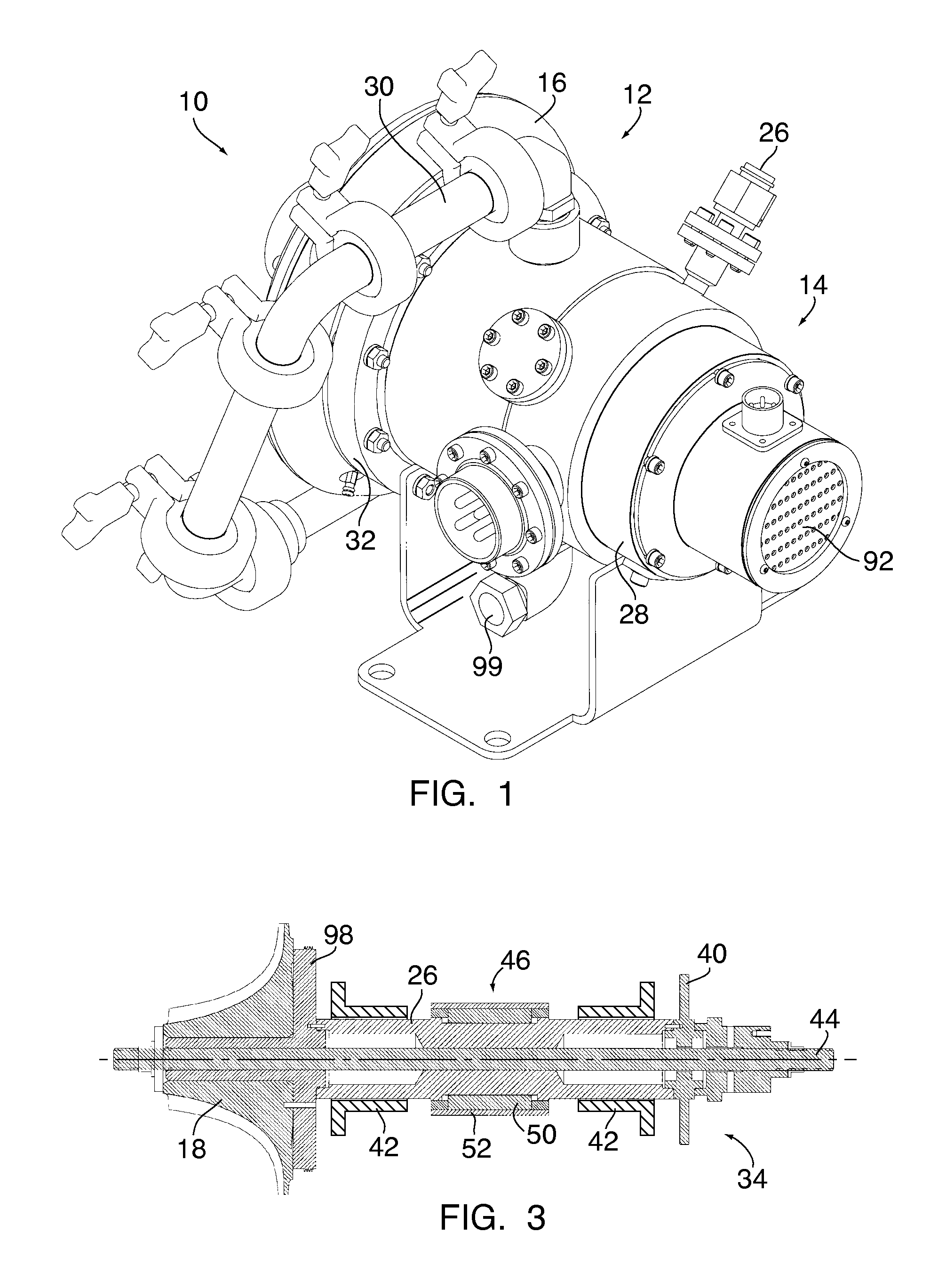
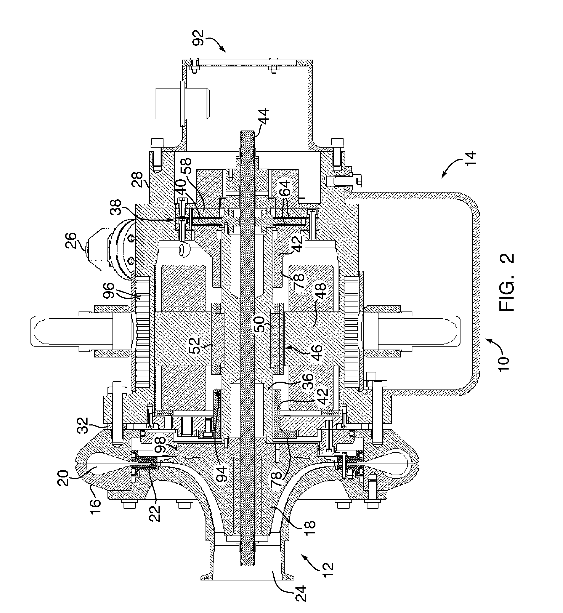
[0042]The present invention is directed to a power generating system for recovering energy stored in a process gas. A perspective view and cross-section of an exemplary turbine-driven alternator in accordance with the present invention, generally designated by reference numeral 10 and hereinafter referred to as “turboalternator 10”, are illustrated in FIGS. 1 and 2, respectively. Turboalternator 10 is preferably a small, high efficiency, oil-free device that can be used in various applications, such as for compressed air energy storage, waste gas energy recovery, pressure letdown, gas liquefaction, and organic Rankine cycles.

[0043]The turboalternator 10 generally comprises a turbine 12 and a generating device 14, such as an alternator or a generator. In general, the turboalternator of the present invention operates the same regardless of whether the generating device is an alternator or a generator. Hereinafter, the generating device 14 is described with reference to a generator. Ho...


PUM

PropertyMeasurementUnit
temperatureaaaaaaaaaa
energyaaaaaaaaaa
electrical energyaaaaaaaaaa

Abstract

This invention provides a small, high efficiency, oil-free turbine-driven alternator (i.e. turboalternator) suitable for conversion of stored energy in a process gas to electrical power, facilitating recapture of energy during operation that would otherwise be wasted. The turboalternator includes a turbine and a generating device operatively connected together by a rotating shaft capable of rotating at high speeds. The rotating shaft is supported by foil gas bearings.

Description

CROSS-REFERENCE TO RELATED APPLICATIONS[0001]This application claims the benefit of U.S. Provisional Application No. 60 / 898,896, filed Feb. 1, 2007, which is incorporated herein by reference.FIELD OF THE INVENTION[0002]The present invention relates generally to turbo-machinery, and more particularly to turbine-driven alternators used to convert the stored energy of a process gas into electrical energy. Such turbine-driven alternators, or turboalternators, may be used in various applications, such as compressed air energy storage (CAES), waste gas energy recovery (WGER), pressure letdown, gas liquefaction, and organic Rankine cycles (ORC).BACKGROUND OF THE INVENTION[0003]Turbine-driven alternators, namely turboalternators, are a key piece of machinery in many different systems for generation of energy. A turbine converts stored energy in a process gas to mechanical energy. An alternator, which is typically coupled to the turbine via a rotating shaft, converts the mechanical energy in...

Claims


Application Information

Patent Timeline
Patent Type & Authority Applications(United States)
IPC IPC(8): H02K7/18F01D25/12F01D25/16
CPCF01D15/005F01D15/10F02C1/02H02K5/1672H02K7/1823F05D2240/53F05D2220/31F05D2220/72F05D2220/764F16C17/024F16C17/045
Inventor AGRAWAL, GIRIDHARI L.BUCKLEY, CHARLES WILLIAM
Owner R & D DYNAMICS
Why Eureka
Try Eureka